

Results 21 to 40 of 49
Thread: 1980 C3 Corvette to LS2/T56
-
09-16-2013, 03:24 AM #21Junior Member

- Join Date
- Nov 2012
- Location
- Nebraska
- Posts
- 27
Red- 1980 Corvette
Leon, Originally Posted by reedld

I had been over to VetteWorks and CustomImage a while ago but it looks like they have some more stuff online then the last time I checked. I have the 1980 tank with a plastic lining so I am reluctant to do any cutting mods. Here is what I fabricated using a Walbro 255 gph in-tank pump, a 58 PSI in-line regulator, and the stock lines.
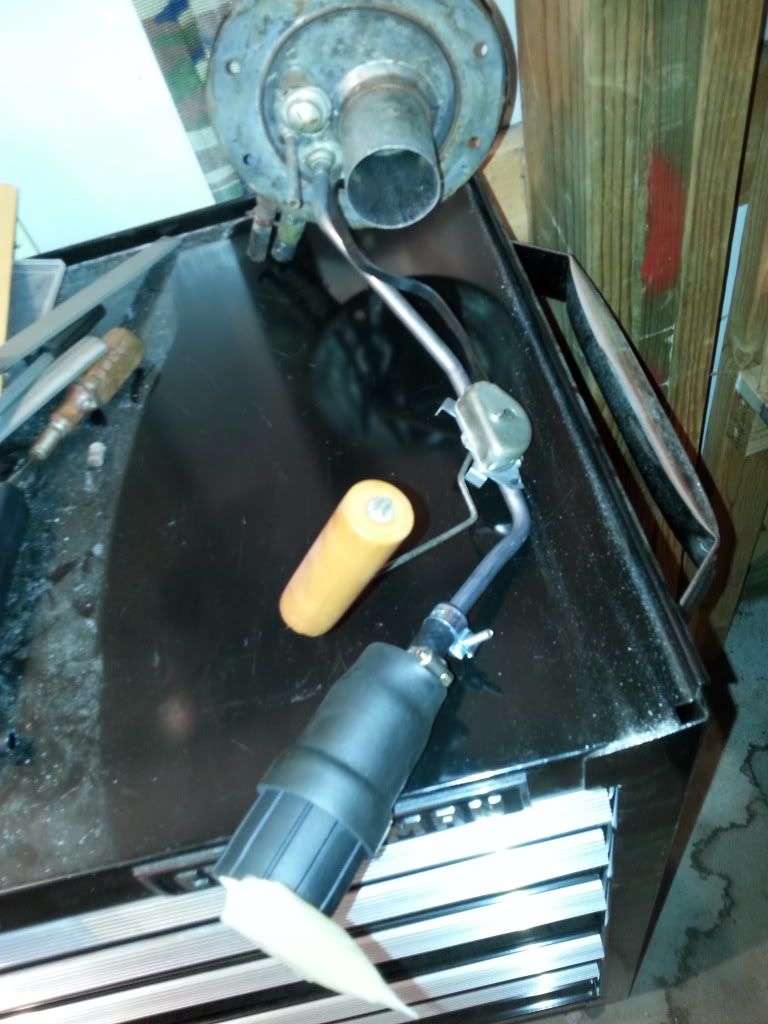
The wiring connections will be outside the tank. Now I need to determine the best route for wiring to have the pump run when the key is turned. And decide if I need to run the ground with the hot wire or ground to the frame. What do you think?
-
09-16-2013, 01:39 PM #22Junior Member

- Join Date
- Oct 2010
- Location
- Painted Post NY
- Posts
- 49
Jetstream Metallic Blue- 1978 Trans Am LS1
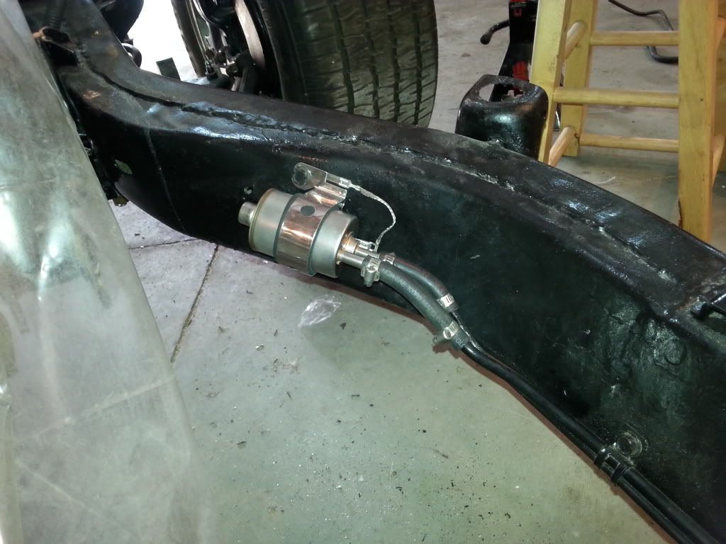
My ground is to the frame...here is a pic of my old setup...NOISEY!!! , but worked well. Originally Posted by Myko
I'd worry about your pump getting hot or sucking air, both will cause the pump to fail prematurely. The OEM setup uses a bucket to prevent this. I don't know if you can put some kind of container in the tank...then put your walbro inside that. It will work without the bucket ...but you will not be able to let your fuel level get low.Last edited by reedld; 09-16-2013 at 02:26 PM.
-
09-16-2013, 03:45 PM #23Junior Member
- Join Date
- Nov 2012
- Location
- Nebraska
- Posts
- 27
Red- 1980 Corvette
I can't imagine a pump getting hotter in the tank then outside it? The NOISE was the major factor for choosing an in tank pump. Originally Posted by reedld
I am still thinking of a way to get the bucket in there. I guess that was what I was thinking of but called it "baffles". Any pics of a homemade bucket?Last edited by Myko; 09-17-2013 at 02:59 AM.
-
09-16-2013, 05:48 PM #24Junior Member
- Join Date
- Oct 2010
- Location
- Painted Post NY
- Posts
- 49
Jetstream Metallic Blue- 1978 Trans Am LS1
The comment about the pump getting hot is only from what I've read...but makes sense the pump, submersed in gas would be cooler, than in open air. I don't know how you would fit a bucket in there without cutting a hole. Is the tank partially plastics? I understand your concern about cutting into a used tank, that's why I bought a new one to modify. Depending on where you live, if you have a radiator shop near by....they may be able to cut a hole in the used tank.
-
09-16-2013, 06:46 PM #25Junior Member
- Join Date
- Nov 2012
- Location
- Nebraska
- Posts
- 27
Red- 1980 Corvette
The tank has a plastic lining. A bladder,so to speak. I could make the existing hole larger but would worry about trying to make a different hole. It would be nearly impossible to weld on the bottom of the tank. An older C3 tank would work to modify, if necessary.
I was trying to think of a bucket design that would fit and attach to the pick up. I'll probably make something. It won't need to be pretty, just effective.
-
09-17-2013, 03:36 AM #26Junior Member
- Join Date
- Oct 2010
- Location
- Painted Post NY
- Posts
- 49
Jetstream Metallic Blue- 1978 Trans Am LS1
I found a pic of the 80 tank with the "bladder" you are referring too. I think the best way to do it is from the top....off to one side like vetteworks did.
-
09-20-2013, 03:15 PM #27Junior Member
- Join Date
- Nov 2012
- Location
- Nebraska
- Posts
- 27
Red- 1980 Corvette
The tanks from Vetteworks and others are made from the older style tanks. I think I'll hook this setup up and check pressure and flow. If it looks good I'll rerun high pressure lines.
I just ordered the radiator so after I get the water pump finished I'll be ready to start it.
-
09-20-2013, 04:37 PM #28Veteran

- Join Date
- Feb 2009
- Location
- Mansfield, PA
- Posts
- 22,146
Black & Blue- '02 WS.6 / '07 Suburban
The joy of installing the C3 radiator. My brand new one leaked after 2-3 years and I had to pull it to get it fixed. Not a real fun job.
-
09-21-2013, 04:41 AM #29Junior Member
- Join Date
- Nov 2012
- Location
- Nebraska
- Posts
- 27
Red- 1980 Corvette
I found a small hole in my original one so I bought an aluminum replacement. I plan to make any adjustments to the brackets needed for easier removal now. The brackets are rusted and will need welded anyway so I might as well plan on the future leaks and put in some time now to make it easier when everything is back together. Originally Posted by pajeff02
-
09-21-2013, 05:23 AM #30Veteran
- Join Date
- Feb 2009
- Location
- Mansfield, PA
- Posts
- 22,146
Black & Blue- '02 WS.6 / '07 Suburban
I went with a copper/brass replacement and it works great. I think it was a seam that leaked on ours, so I had it repaired. While it was out of the car, I bent the outlet up to gain some more clearance by the front suspension and fan shroud, and then had that re-soldered as well. That has been at least 4 years ago and it has held up well.
Here's my C3 puzzler -- on startup, the headlights on our car go up and down. Everything has been replaced in the headlight system, including the switch, canisters, and diverter valve. No idea why it does this. Last time I drove the car, the driver side headlight actually opened and closed twice when I started it.
-
09-21-2013, 08:34 AM #31Junior Member
- Join Date
- Nov 2012
- Location
- Nebraska
- Posts
- 27
Red- 1980 Corvette
Sounds like a leak. If they go up and down multiple times there must be a leak in at least one of the circuits. Do they work when you turn them on?
There are a million headlight threads on the Corvette forums for diagrams, etc.
-
09-21-2013, 12:26 PM #32Veteran
- Join Date
- Feb 2009
- Location
- Mansfield, PA
- Posts
- 22,146
Black & Blue- '02 WS.6 / '07 Suburban
I just downloaded a headlight diagnostic. They work just fine when the light switch is turned on and they go down when the switch is turned off. Not a clue why they cycle like that.
-
10-02-2013, 03:54 AM #33Junior Member
- Join Date
- Nov 2012
- Location
- Nebraska
- Posts
- 27
Red- 1980 Corvette
On to wiring... Scary.
The dual fans and fuel pump are my first big concerns. Yes, I know I can buy a $500-1000 wiring harness that will avoid most issues. I am planning to use some GTO gauges (speedo, tach, odo) and some original Corvette gauges. I am also unsure about A/C, cruise control, and security features at this time. So, I want to explore the option of using my OEM harness with an additional under hood fuse box for the additional components.
Does anyone have information about using my GTO ECU/PCM for the fans and fuel pump relays? Wiring diagrams are helpful but some additional instruction would be even more useful.
Thanks,
Mike
-
10-02-2013, 05:54 PM #34Veteran
- Join Date
- Feb 2009
- Location
- Mansfield, PA
- Posts
- 22,146
Black & Blue- '02 WS.6 / '07 Suburban
I would need a schematic to see how they accomplish it through the ECM. Maybe just keep it simple -- you need a fan temperature switch that comes on around 10 to 15 degrees hotter than your thermostat's rating and a relay (or two) to handle the high current draw for the fans. Assuming that your fan temp switch closes a ground, you will run fused power to the relay trigger that is hot with the ignition on, the ground trigger will be attached to the temp switch, heavy gauge fused wire will feed the input side of the relay and the fans will be attached to the other side.
-
10-04-2013, 02:40 AM #35Junior Member
- Join Date
- Nov 2012
- Location
- Nebraska
- Posts
- 27
Red- 1980 Corvette
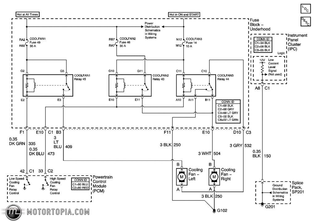
Here is the schematic but it doesn't give any detail on how/where to plug into the PCM. I don't have any problem wiring the fans outside the ECU, and may get a Painless harness to make it simple. I am trying to figure out how to get the temp gauge to work.
I am more worried about the fuel pump and problems with the VATS. If it is wired independent of the ECU can you just program the car to "forget" about the pump?Last edited by Myko; 10-04-2013 at 02:47 AM. Reason: Trying to stop pic from being re-sized to a thumbnail.
-
10-05-2013, 03:45 AM #36Veteran
- Join Date
- Feb 2009
- Location
- Mansfield, PA
- Posts
- 22,146
Black & Blue- '02 WS.6 / '07 Suburban
C1 is connector 1 and C2 is connector 2 at the PCM. You would simply splice into that wire and connect it to your relay on the trigger side. I'd have to look to see if the PCM is sending voltage or a ground signal.
-
10-05-2013, 04:57 AM #37Junior Member
- Join Date
- Nov 2012
- Location
- Nebraska
- Posts
- 27
Red- 1980 Corvette
The outputs are grounds for the relays. I have 30/40 5 prong relays that I thought would be needed but I'm a little confused after looking at the fans. Each fan has only two wires. Why are there 3 fans in the diagram, each with a different relay? I thought the temp sender would make the connection to operate a trinary relay on fan 2, not to operate the relay on all 3. Is fan 1 always on, fan 2 on low, and fan 3 just higher speed?
-
10-05-2013, 06:24 AM #38Veteran
- Join Date
- Feb 2009
- Location
- Mansfield, PA
- Posts
- 22,146
Black & Blue- '02 WS.6 / '07 Suburban
That third relay is the ground for Fan 1. Not a clue why they wire it like that.
-
10-08-2013, 06:27 PM #39Junior Member
- Join Date
- Nov 2012
- Location
- Nebraska
- Posts
- 27
Red- 1980 Corvette
Could it be that the larger fan on the right is dual speed? I thought fan 1 was constant, fan 2 and 3 were low and high speed on the Cooling Fan - Right. Could this be done in an A/C car if the fans each only have a hot and a ground wire?
-
10-09-2013, 02:57 AM #40Veteran
- Join Date
- Feb 2009
- Location
- Mansfield, PA
- Posts
- 22,146
Black & Blue- '02 WS.6 / '07 Suburban
If you trace the schematic from each relay, you see power to each fan and then that third one controls a ground circuit. Not a clue what they are doing. I could check my manuals to see if there is an explanation of the fan circuit and then post it for you.


 Reply With Quote
Thread Information
Users Browsing this Thread
There are currently 1 users browsing this thread. (0 members and 1 guests)
Similar Threads
-
Question: LS1 into 1980 C3 Corvette, Fuel vapour canister requirement?
By mysticpete in forum LSx Retrofit and SwapReplies: 2Last Post: 11-18-2014, 09:01 PM -
1980 Chevrolet Corvette - Rides
By Ed Blown Vert in forum Camaro / SSReplies: 0Last Post: 04-16-2012, 10:30 PM -
LSX into 1980 C3 Corvette
By c380vette in forum Classic MuscleReplies: 6Last Post: 08-17-2008, 08:24 PM -
1980 3/4 Ton Chev
By oldsdrvr72 in forum Vehicles For Sale / TradeReplies: 2Last Post: 05-12-2006, 09:32 AM -
1980 Z28
By BlueEyedDevil141 in forum Vehicles For Sale / TradeReplies: 18Last Post: 09-03-2005, 03:48 PM

Bookmarks