
Results 1 to 8 of 8
-
05-21-2013, 05:29 PM #1Junior Member

- Join Date
- Sep 2012
- Location
- Ohio
- Posts
- 15
Blue Green Chameleon- 1999 Pontiac Trans Am
Permanent Wideband Install Write Up, Lots of Pictures
Alright, I’m doing this write up because when I first bought my wideband I was looking like crazy to get ideas on how and where to run the wires to set this up for a street car. I wanted to have it in there all the time, and have everything ran so I wouldn’t have any issues. I want to put a bunch of information all in one place to help people out by not having to look for hours on end to come up with ideas for a month in their head until they get brave enough to try one.
Btw I know my car is dirrrrrrrrrrrrrrrrttty underneath.
I didn’t really take any pictures during the install, so I can’t really show how it was done the whole way through, but I do have some pictures of how it is set up finished.
Disclaimer, I’m not liable for anything stupid you do, or anything that gets broke, messed up, damaged, or anyone that gets hurt. You’re doing the work and if I did something unsafe or not how you want it don’t do it, you’re a big boy/girl.
I would recommend after reading this to spend a few days researching how everyone else did it, and research your specific WB/CAR/Tuning software because if it is not the same as mine, it may not work the way I have it set up. But the general idea of how I wired the wideband should work for about anything.
ITEMS:
Some tools
A wideband
Soldering gun
Inline fuse holder
Hptuners(or any tuning program)
A fuse
Electrical tape
Round ends for the wire
Wire strippers
Cordless Drill
Drill Bit
Circle Drill Thing
Rubber Stopper
Relay Socket for your relay
A Cube Relay ( I used this 782-2C-12D CUBE RELAY 15A DPDT 12VDC COIL LED INDICATOR TEST PUSHBUTTON (LINK TO RELAY I USED))
Time
Money
Beer
Patience
Extra 18 gauge wire
Splice Connector
Heat shrink tube for connections
Screw Drivers
Zip Ties
I ended up getting the NGK AFX wideband. The first thing I did was see how long all the wiring was, and looked at how they had the wires set up. There was one plug on an end that went into the controller, and two other ends. One had a plug that went into the sensor, the other had a power and two ground wires. Now there was more than enough wiring to do everything I wanted so that was not an issue.
First thing I did was disconnect both battery terminals, took the bolts out of the end of the wires, and took the rubber boots off. Then I cut both ends off of the power and ground wires that were on the wideband’s wiring kit. I went to a autoparts store and found some loop wire ends that the bolts fit through, I don’t remember the exact size. Went home and put one on the end of the ground wire crimped it, then I put it up next to the loop on the battery wire. Now this was probably the hardest, longest, and most frustrating part. I had to find a way to slide the boot on with both of those in there, while being careful not to move or bend the one on the end of the wideband wiring. As soon as I got that done, I had extreme fun (sarcasm) getting the bolt back in. But as soon as it is done it looks like it belongs and isn’t tacky.
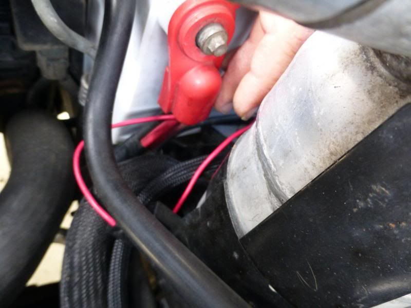
This is the ground wire but you get the idea.
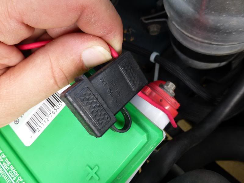
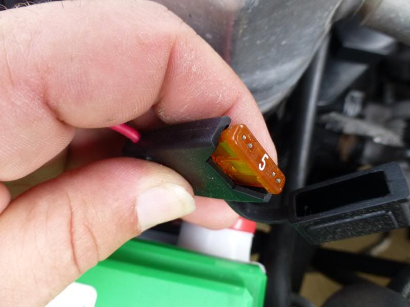
For the positive side, I didn’t put the end loop end on right away, I went to radio shack and bought a outside inline fuse and I soldered that to the wideband wire and put shrink tubing around it to seal it, and then put the loop connector on the end of that and ran it to the battery. This way there is only a couple of inches of power wire not protected by a fuse. I used a 5A fuse because NGK said it won’t draw more than about 3A of power. If using a different wideband check how much current it draws.
-
05-23-2013, 01:03 PM #2Junior Member
- Join Date
- Sep 2012
- Location
- Ohio
- Posts
- 15
Blue Green Chameleon- 1999 Pontiac Trans Am
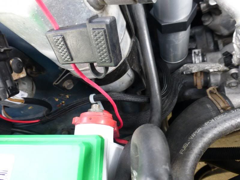
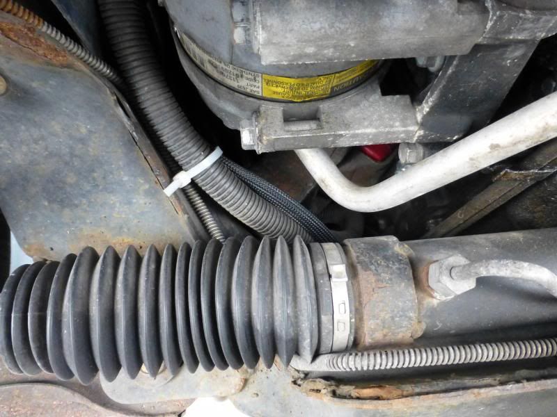
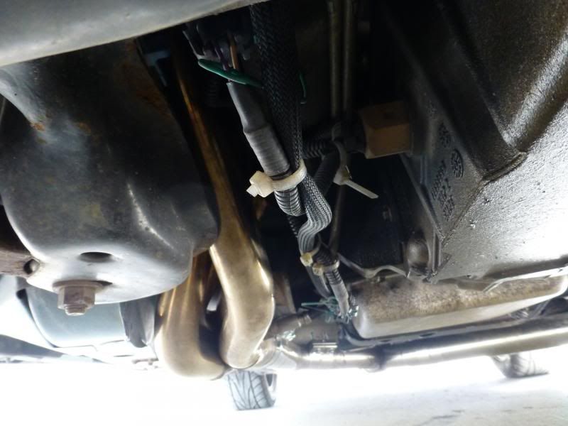
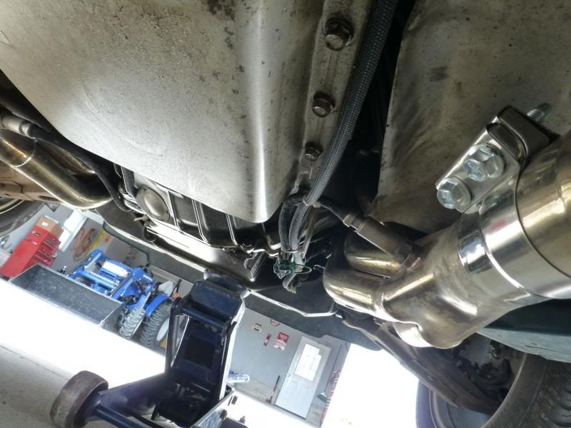
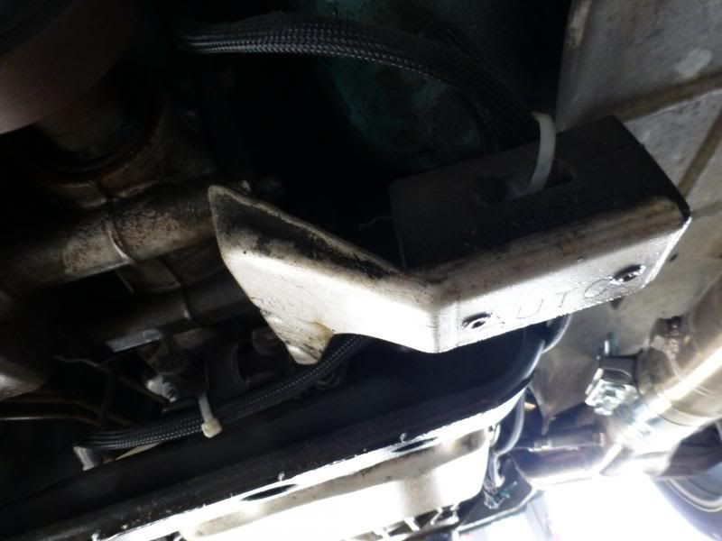
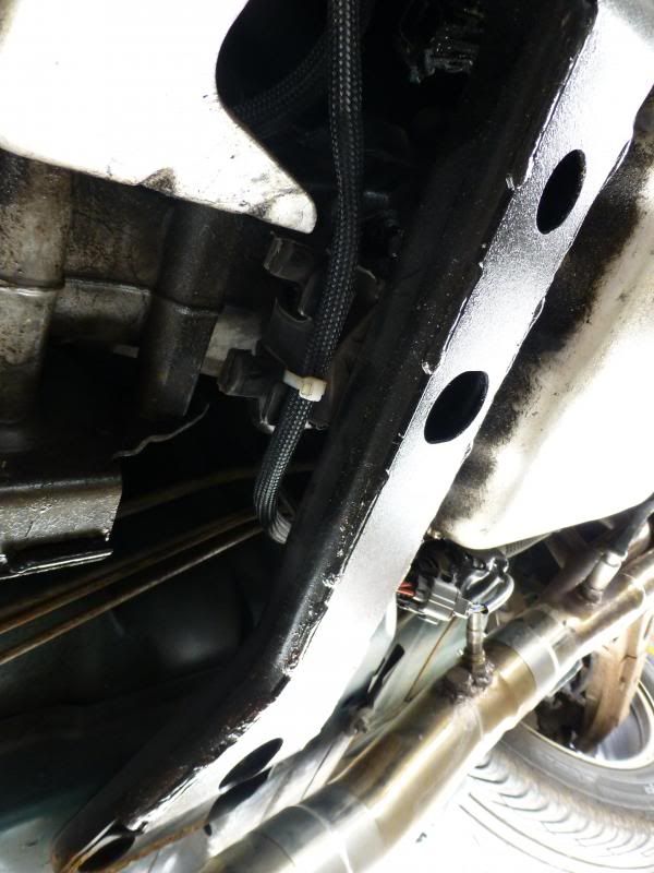
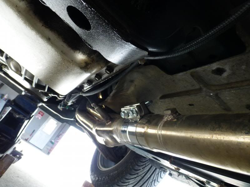
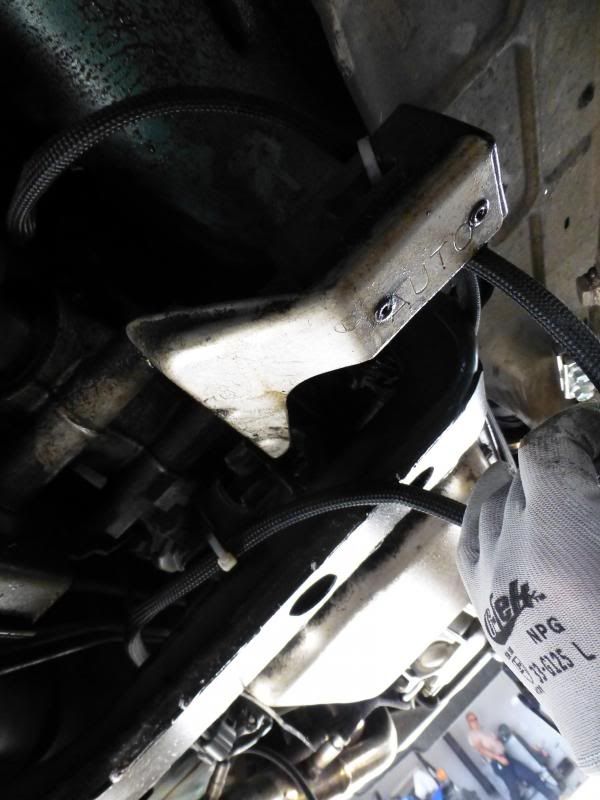
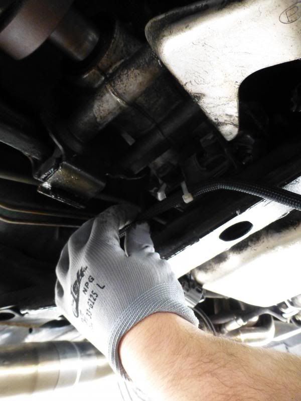
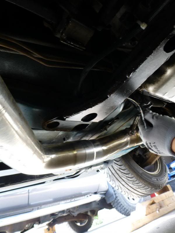
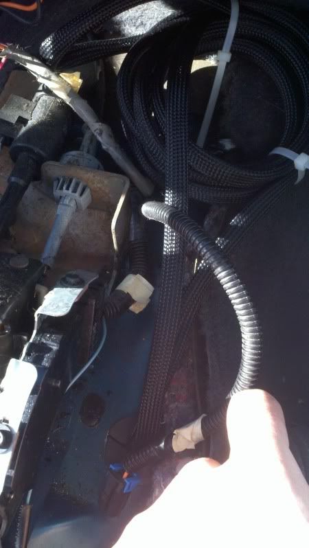
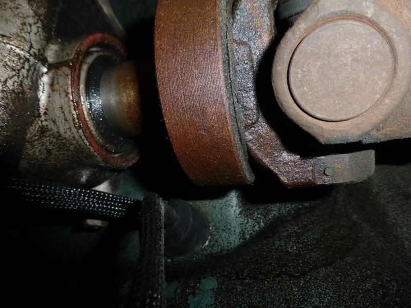
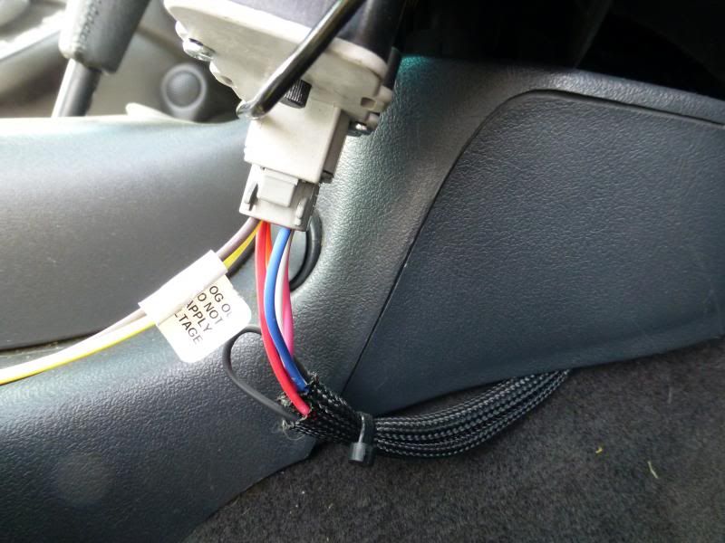
Now this is the path starting from the fuse area that I ran the wire. I started with the bundle down at the bottom and got a long metal fire stirring rod that had an L-bend at the one end, had my brother feed it from the top down, and tapped or ziptied the power end to that and pulled it up by the battery. Then I took the wire and made sure it was away from any heat and basically ziptied it in safe spots…not tight yet, so I could still pull it through to get it set up the way I wanted. I followed the wiring for the stock o2 sensors back to where my exhaust y-pipe had originally been hung from.
-
05-23-2013, 01:05 PM #3Junior Member
- Join Date
- Sep 2012
- Location
- Ohio
- Posts
- 15
Blue Green Chameleon- 1999 Pontiac Trans Am
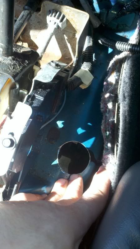
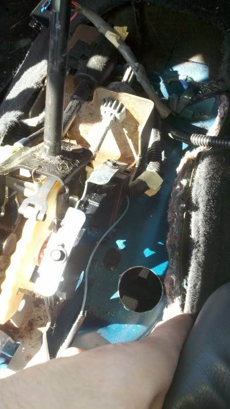
Now for the hole, I had to remove the center consul. I believe there were two bolts facing sideways up under the dash by the floor, pull the change holder out, there were some under that, Need to take the handle off the shifter and put that in neutral. Pull up the parking brake, and then using a pick or something pull up a locking mechanism on the ratchet gear, and the handle can go up pretty much straight then. Take off the middle piece that goes around the shifter. I think there was a small light in the bottom that you need to make sure you take out so you don’t break it. I think there was a bolt under that, and then two bolds inside the center consul.
Just search around, I know there was a thread with some pictures to help…its really not to hard, just don’t break any of the connectors to the switches or lights.
After that is out, I kind of cleaned up under there, the previous owner was messy. I didn’t really have much time to do much cleaning, but got most of it. I then took a smaller drill bit and put a hole where I thought would be a good place where it wouldn’t hit anything (you need to look at the top, then go underneath and look above the tranny to see how the arch of the trans tunnel looks compared to where stuff is). I then took (not sure what its called exactly) but one of those hole cutters with the drill bit in the middle to guide it that goes in a hand held drill.
http://3.bp.blogspot.com/-paFuDGvZJP...0/IMG_4459.JPG
http://i.ebayimg.com/t/11pc-Holesaw-Drill-Bits-Circle-Saw-Set-Drills-Cutters-/12/!BpT8EqQ!2k~$(KGrHqQOKjoEu,h,DsM0BLq1+Vig,!~~_35.J PG
Like those above.
I don’t remember the size that I used, but we compared it to the plug that goes into the back of the wideband controller. As long as that fitted I was happy. I drilled out a hole and double checked the placement. Filed down any burrs or sharp spots. I then went down under the car and fed up the plug to my brother which pulled a bunch of the wire through the hole so I didn’t have a mess under the car. I figured any extra wire is safer under the center consul instead of hanging under the car.
- - - Updated - - -
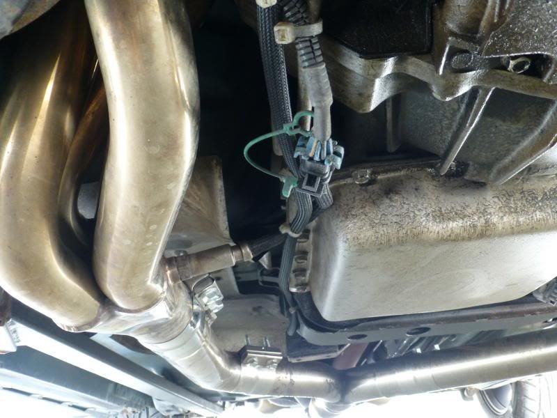
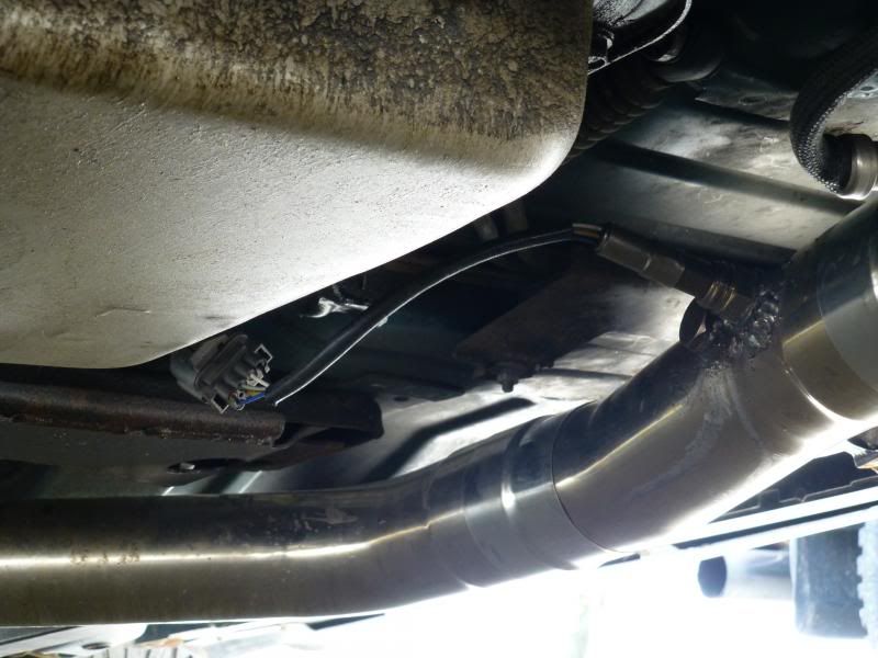
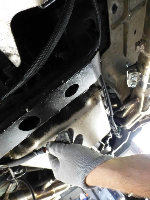
I got as much wire as I wanted underneath and ran it where I wanted, so nothing could catch it, and put zipties to hold it in place….again not tight yet. I had it set to where I could run the sensor end to either bank, yet have some slack if I needed it but left the zipties somewhat loose in the middle of the car so I could pull slack through to get any hanging wires up. Most of the zipties from the battery back to the exhaust hanger I ended up pulling tight and cutting the ends off of them.
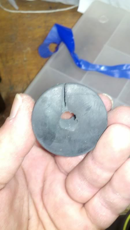
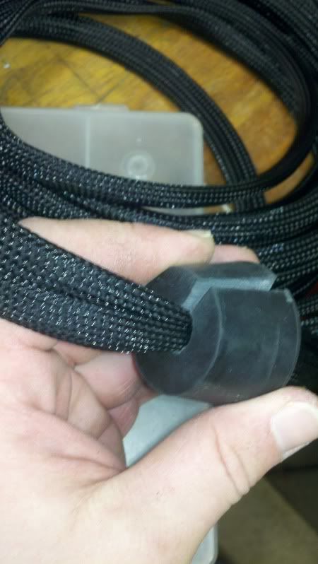
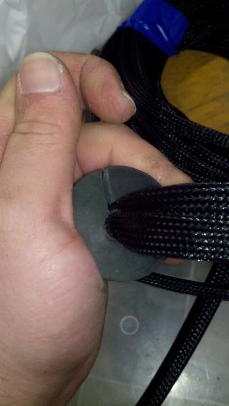
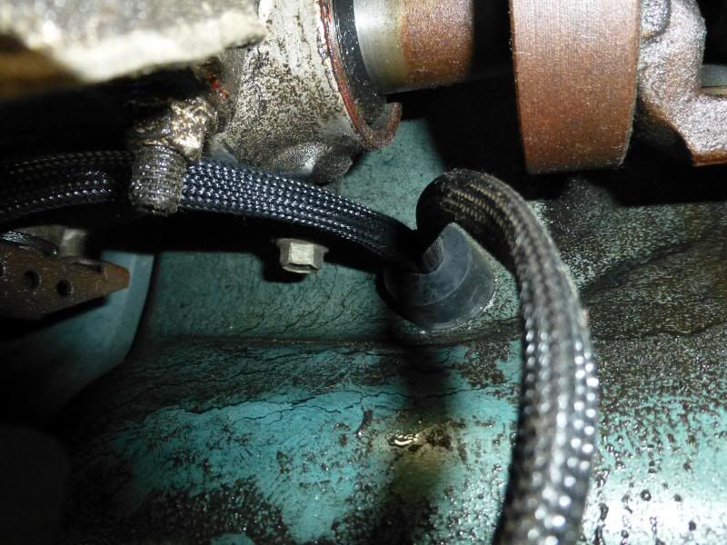
To plug the hole I had created, it was kind of a trick. I had a guy at ace hardware suggest a stopper…then he was like “oh yeah, need to run the plug and wires through it” we thought for a while on what to use because they didn’t have much in the same size as the hole. Then it clicked in my head, take the stopper, drill a hold about the size of the wires in the middle, put the stopper in a vice and use a hack saw to cut down to the hole on a side, then I could peal it open around the wires and then when I plugged the hole it would push it tight and hold the wires in place as well as sealing the hole.
-
05-23-2013, 01:07 PM #4Junior Member
- Join Date
- Sep 2012
- Location
- Ohio
- Posts
- 15
Blue Green Chameleon- 1999 Pontiac Trans Am
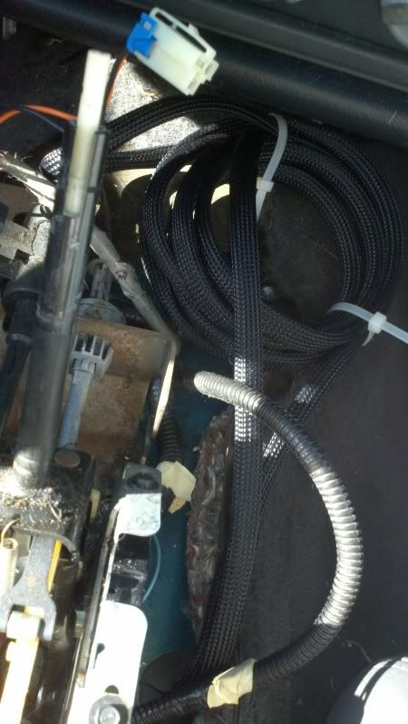
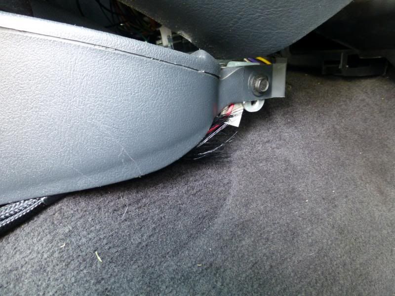
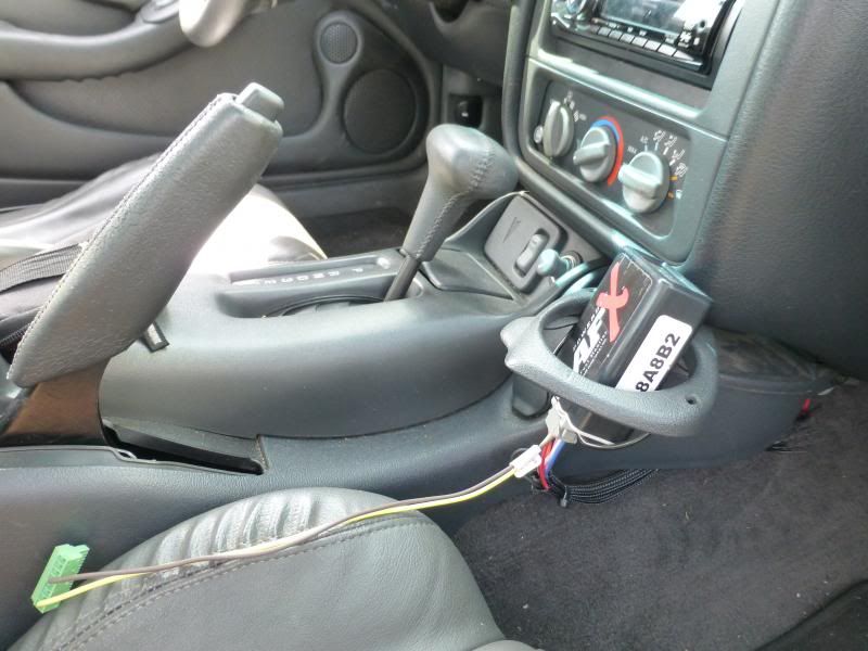
Alright, now for the inside of the car. I took and left out as much wire as I need to put the controller where I wanted, and I took the extra wire and wound it up and used a twisty tie to hold it together and left it spooled up under the front of the center consul. I ran the plug end out of the front passenger side of the center consul where the one bolt went.
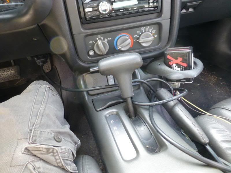
Now to control when it turned on and off I didn’t want to have to worry about a switch. If I would forget it may get carbon build up or foul out due to the heat being turned off. So I got a cube relay, and a socket for the relay. I figured this would be able to turn it on and off and the socket is nice because if the relay goes bad I buy a new one and it’s a ten second swap. Also what most people don’t realize that is nice, especially with the ngk afx, is that to calibrate it you need to let it hang in open air and be turned on. With relay I can flip the test switch at the top and I can turn it on and leave it on without turning the ignition on.
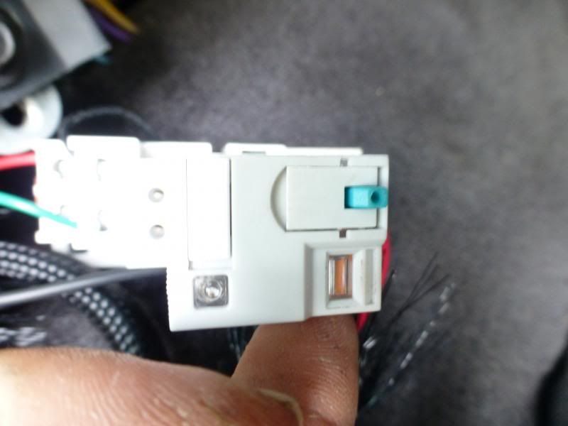

It tucks up in there nicely.
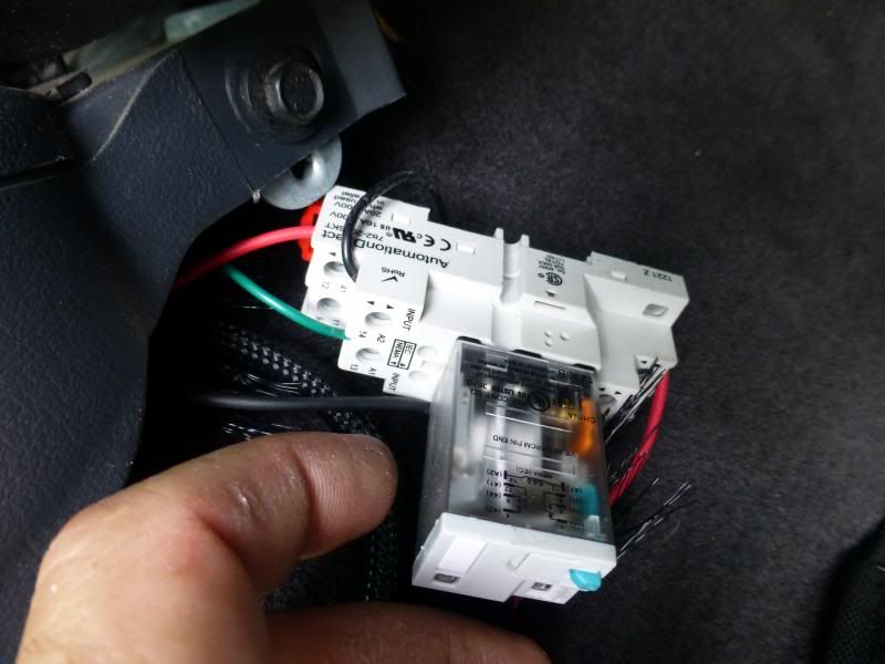
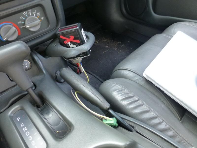
I had to figure out where to wire the relay to so I would make sure every time I turned the ignition on it would come on, so I chose wiring it to the radio power. I also figured since the radio stays on after you turn the key off it would allow it to stay heated to burn any gas fumes off that may come down after the car is turned off. So I just spliced into that wire and ran it to the relay socket and put connected it to the one that ran to the coil.
Just looking at the green wire going to the red one, not sure whats going to my ground, was like that when I got it.
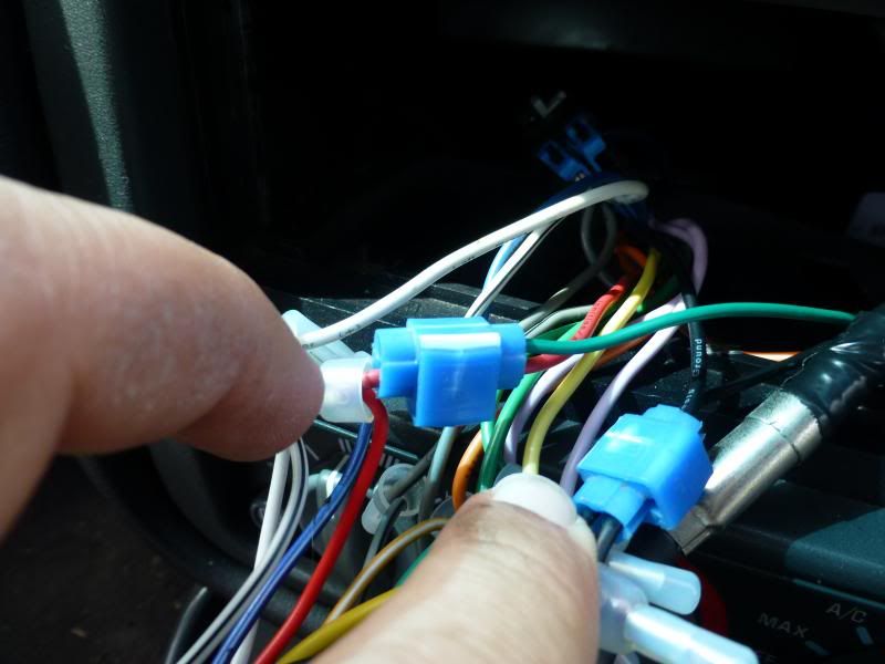
To get the relay in to the power, I had to cut the sleeve around the wires and cut the power wire to the controller and run it through the relay socket. I planned on taping up the frayed ends of the sleeve to the wire to make it more aesthetically pleasing but never got around to it. Also when cutting the sleeve, BE VERY CAREFUL NOT TO CUT ANY OF THE WIRES OR NIC THEM. I moved all wires to one side, cut a slit in the other side and used scissors to trim around without getting the wires. Now you want the power going in one side, but not being connected when the powers off to where it comes out. You’ll have to look at the diagram on the relay and figure it out yourself, I don’t really remember how it goes by the pictures on the relay. But when the power is turned on, goes to the radio, from there you get power to the coil on the relay, which flips the switch inside, and completes the circuit and allows the wide band to get power. Makes it nice not having to worry about always turning on or turning off the wide band. Its all automatic.
- - - Updated - - -
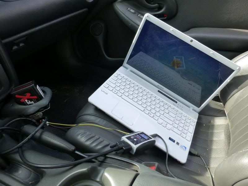
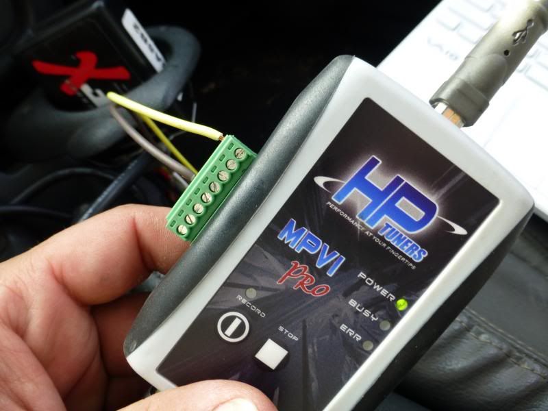
Now I didn’t leave much room from the relay to the end of the plug, so I couldn’t mount the controller to far away from where it came out from under the center consul, so I just stuck it in the cup holder. I just sit my laptop in the passenger seat, or have a buddy hold it, run the hptuner cable up to the odb2 port, and hook in the wide band to my pro interface right next to the hand brake.
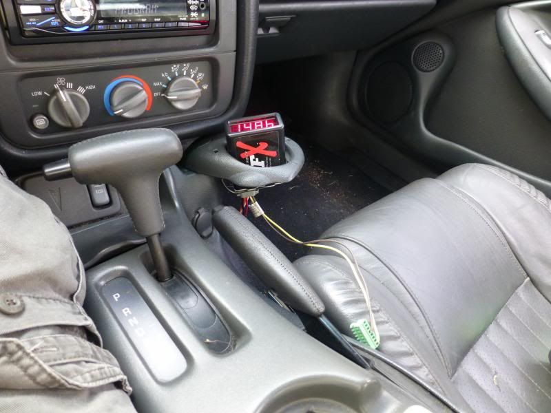
To calibrate the wideband in “free air” which you need to do before you use it, I just ran the wire so the sensor wouldn’t touch the ground but would hang about an inch off above it so the breeze would go by to give it fresh air. Then I would follow the instructions about turning the knob on the back of the controller all the way to one direction, flip the test switch on the relay, made sure it came on, the sensor started warming up (don’t touch it, it’s hot and can burn you) then went and did other stuff for awhile. Don’t have any pictures but I’m sure you can figure it out, if not your probably not this far anyways.
-
05-23-2013, 01:07 PM #5Junior Member
- Join Date
- Sep 2012
- Location
- Ohio
- Posts
- 15
Blue Green Chameleon- 1999 Pontiac Trans Am
Now I’ll briefly go through setting it up in hptuners. Its been awhile so I hope I remember how I did this, and I show it right.
BEFORE using the data collected to tune your ve table make sure you follow one of the guides online to set your car up to run in open loop speed density. This way the computer doesn’t make corrections based on readings from the MAF or o2 sensors. Also it prevents other fueling modifiers from screwing up data being collected…ie cat over heat protection would add fuel to protect cats from being cooked, and would show up as a leaner condition that is false, making your ve in those cells be a lower number than what they should be…showing that your motor is less efficient at pumping air at that level, and if that’s deactivated later, it would cause a lean spot/condition.
First I searched around to find out how to set up the PID in the tuner, like the equation. I ended up going with one that I found because it seemed most people agreed with him, and he seemed to know what he was talking about. Here is the thread I used to determine how to set up MY wideband, the ngk afx. I started off with the equation that DSTECK suggested. V/10.41 + 0.62
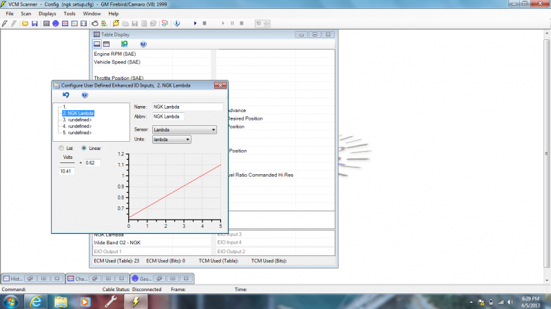
Now to test this I found its best to leave the sensor out of the car and don’t start it, after calibration of course. This way it is at max afr, in my case 16afr. A quick check on the controller box confirms this. Now since the sensor is a 0-5v sensor, 0=9afr or ~.62 lambda and 5=16afr or ~1.10 lambda.You can use that formula above to calculate the lambda (which is easier to use than afr because your aiming for “1” which is the commanded afr, which depends on the fuel being used)
While doing my research I seen where people made a good point about the max voltage from the sensor. It says it is 5v but you will never get it. When using the above formula at 16afr it should have been 5v but was only getting a lambda of 1.07, so evidently I wasn’t getting the full 5v. I had to do some calculations to get the formula right.
Original formula was =v/10.41+0.62. So at 5v it should be at a 16afr or 1.10 lambda in hptuners.
I only got 1.07. So that means I am not at exactly 5v.
So 1.07=v/10.41+0.62. Do some math and v=4.6845v
So 1.10 lambda would need to be like this, because the 0.62 stays the same due to if there is 0 it is a .62 lambda.
1.10=4.6845/x+0.62, x=9.759
Using this new equation 16afr on the controller displayed a 1.1 lambda on hptuners which is corrected so all my other values are fixed. If left uncorrected everything will be off by a percentage.
-
05-23-2013, 01:09 PM #6Junior Member
- Join Date
- Sep 2012
- Location
- Ohio
- Posts
- 15
Blue Green Chameleon- 1999 Pontiac Trans Am
So now the config needs to be set up so you have everything you need, but don’t waste bits of data through the cable…if you have to much you don’t get as good of resolution.
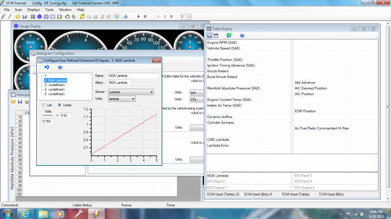
You need to set up CMD Lambda (commanded Lambda) which is just your “Air Fuel Ratio Commanded Hi Res”/whatever your stoich for the fuel is. For mine I was using regular gas, so it was 14.7(can get the more exact number by going into the editor, and looking under the engine tab). Mine looks like this [PID.6001]/14.62857
Now you need to make a lambda error pid, the formula I used was 100*([AUX.20122]-[USER.9004])/[USER.9004]. I think this was the aux=the pid for my wideband I created first, and the user should be the cmdlambda.
You need to make sure where it says user.9004 and such, that you put the right one in that you created, because if its not in the same spot it would get referenced correctly. Somewhere there is a list that you can pull down that shows you what each pid is and what the reference name is. (found it, it’s the blue “?” bubble next to Function when you are making the pid)
Now double check everything to make sure hptuners is displaying the correct lambda, in my case since afx display reads 14.5 at a afr of 14.7 I just add .2 to whatever it reads, then divide it by 14.7 and it should be the same as the lambda read out on the laptop. If not, your math is off and needs adjusted/fixed.
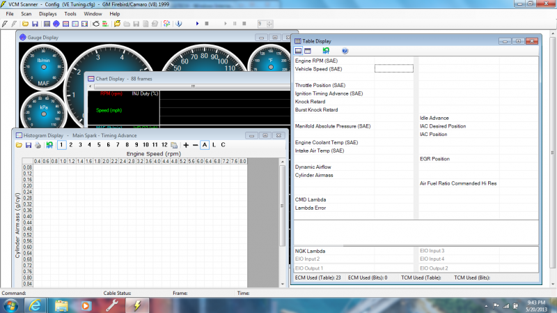
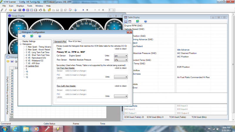
To log a histogram to find out where you need to make changes to your ve table you need to make one based off of lambda error compared to map pressure and rpm. Here are some pictures of how mine is set up. You can also tell how many hits you need in a cell before it logs the data, this is helpful because you can set it higher than one. With only one hit to get data in a cell, it could be inaccurate because of sudden changes in throttle and it may be a runoff from another cell, so your best bet is to at least set it to 7-10 hits. More than this is usually better, your data is more accurate, but the only problem is some cells are hard to get more than say 5 hits in before it jumps to another cell, so there will be gaps in your data. You can always start out with a higher hit count, then lower it after you get some solid data to base your tuning off of. This way you can help to fill in any gaps.
Here are some pictures of how mine is set up.

Now after some logging go all the way to the end of your log to see your data you collected in its entirety.
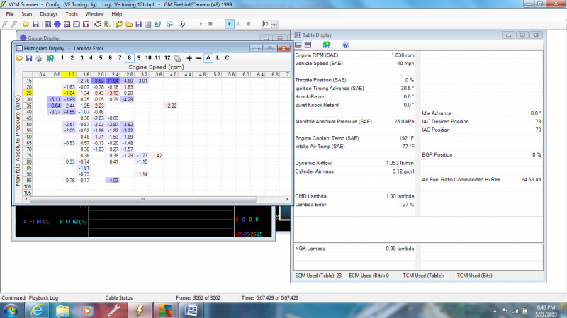
As you can see with this example, my car was running really rich across most of the board and needs to be adjusted, and in some cases by quite a bit.
The histogram is showing you by how many percent your fueling is off. A 4.53 would mean 4.53% lean, or a -9.23 would be -9.23 richer than what the computer is commanding it to be. You can use your histogram to fix this. It comes down to you doing some logging, preferably longer is better to collect more data. I also found that if I slow down to like 30mph in over drive, then give some throttle and feather it not to go to far for it to down shift, and not to go to much and cause a rapid change. I can go from 30-75mph (what ever you feel is safe) and log lower rpm at a higher load. I do that a few times to get some data collected, then I shift it into 3rd and do the same thing. This gets me some higher rpm data, and you can do it in 2nd even too. Just remember nice, smooth and slow throttle changes at first, get some good data.
You can use this data collected by selecting groups of cells that are way off (I usually pick them all together if they are more than 1.5 off) and copy and special paste into the same ve cells in the editor by percent. Then the ones that are lower I copy by percent half. I do this in the primary ve table, then in the secondary, I select each row one at a time from the corrected primary ve table and copy into the secondary. This way I know it copied and it copied the same.
Don’t click in a cell either and enter a number, because if you click the add more button that has a .000 with an arrow (I think that’s what it was) it will show that here are quite a few decimal places behind the number you see….it’s not all rounded off like it appears.
Don’t do any tuning before you read up other threads and read through the tuning guides. I just want to help point you in the right direction and give you the information that you need that the guides leave out, or people forget to mention. A lot of people out there leave out some of this stuff because they are assuming you know what you’re doing at all of the steps in between. But if your like me and your new to this, or someone that has done it already but didn’t think to try it this way, this guide should help you get an idea of where to start. BUT LIKE I SAID, DO RESEARCH AND LEARN AS MUCH AS POSSIBLE BEFORE YOU TUNE.
- - - Updated - - -
I skimmed it to proof read this, so I’m sure there are grammar errors present, and I hope I didn’t leave anything out, or jump ideas in mid paragraph while explaining one step. If so let me know and ill fix it.
Thanks and I hope this helps a lot of people out, and helps get the ball rolling on learning how to tune.
This is me giving something back for all the people that have helped me so far and that will help me down the road.
And once again, do more research before you take on a project or start tuning...gain as much knowledge that you can before hand.
-
05-25-2013, 08:31 AM #7She Moderator

- Join Date
- Jul 2008
- Location
- So Cal
- Age
- 60
- Posts
- 15,660
Arctic White- 2000 Camaro Z28
Thank you for taking the time it took to put this together for our members.
-
03-18-2014, 10:58 AM #8Member

- Join Date
- Mar 2014
- Location
- Midland, Texas, United States
- Posts
- 111
White- 2002 WS6
This is going to come in real handy for me, thanks!!!
10secWS6 If you can't swing it, then don't bring it


 Reply With Quote


Thread Information
Users Browsing this Thread
There are currently 1 users browsing this thread. (0 members and 1 guests)
Similar Threads
-
How to install gauges - Write up
By Hi-Po in forum General HelpReplies: 14Last Post: 11-07-2010, 12:05 PM -
wideband install??
By 02Ls1Formula in forum Computer & TuningReplies: 7Last Post: 01-19-2008, 08:37 AM -
write up on pacesetters install?
By GottaHaveLS1 in forum External EngineReplies: 1Last Post: 07-15-2007, 07:42 PM -
Clutch install write up
By JonB in forum Manual TransmissionReplies: 3Last Post: 06-28-2007, 12:39 PM -
need a write-up on TC install
By Wheeler99WS6 in forum Automatic TransmissionReplies: 10Last Post: 02-18-2007, 04:00 AM

Bookmarks