
Results 1 to 20 of 99
Thread: LC-1 install
-
03-17-2009, 08:57 PM #1Veteran


- Join Date
- Aug 2005
- Location
- ohio
- Posts
- 22,554
98 Formula- 06 duramax
LC-1 install
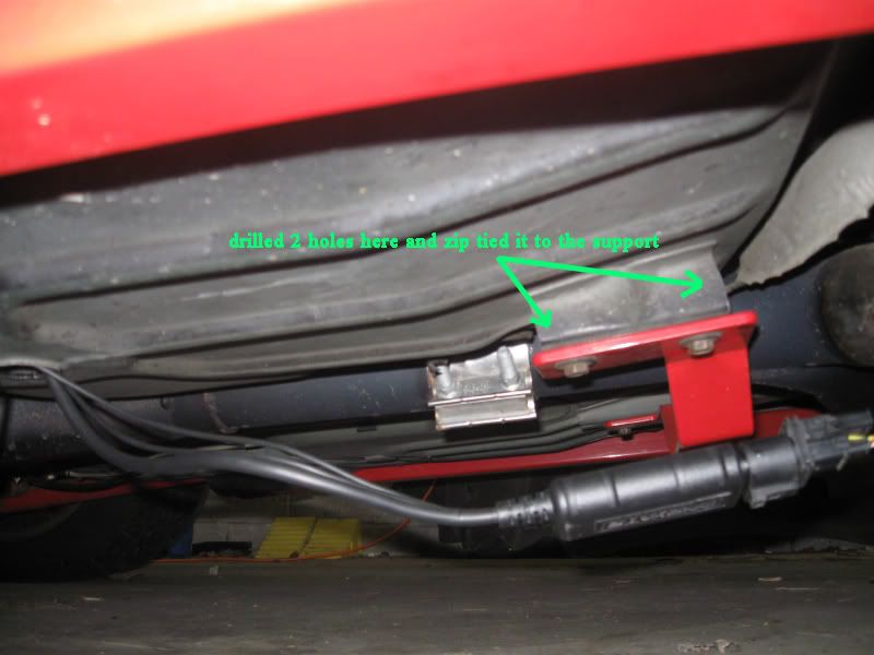
Finished up my LC-1 install today. Took a few pics along the way. The install didn't come out quite as clean as I intended but towards the end I just got tired of messing with it and wanted it finished. Car is dirty.... I know. I did do a heater and free air calibration and everything was fine but I've yet to log with it to test it out and make sure everything is copacetic. Jury is still out on my grounding block until I test it. I'll probably blow everything up the first time I run the car and if I do I'll update the thread accordingly.

It was easier for me to run it back to the grommet behind the passenger seat where my cutout is. The drawback is I had to extend the harness but honestly the harness was going to need extended somewhere anyhow to reach all the grounds and the gauge.
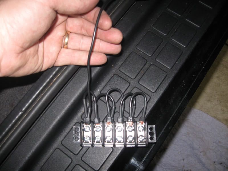
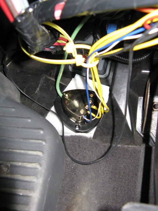
Speaking of grounds. This is the distribution block I made from a junction block so I could ground everything in 1 spot and only have to run 1 wire out to the passenger head to ground.
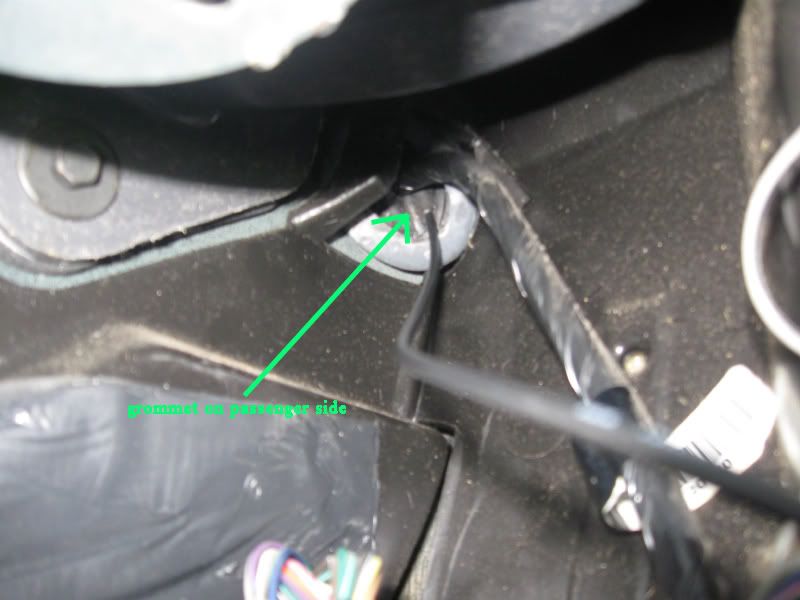
ran wire through this grommet on the passenger side
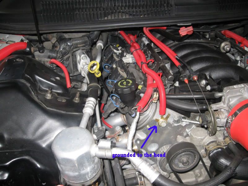
Wire grounded to the front of the head
I drew 12v switched power from the fuse panel. I used the open IGN spot for the wideband and gauge and I have my cutout in the acc spot.
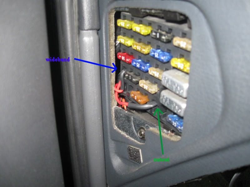
Fused the wire and zipped it in the column
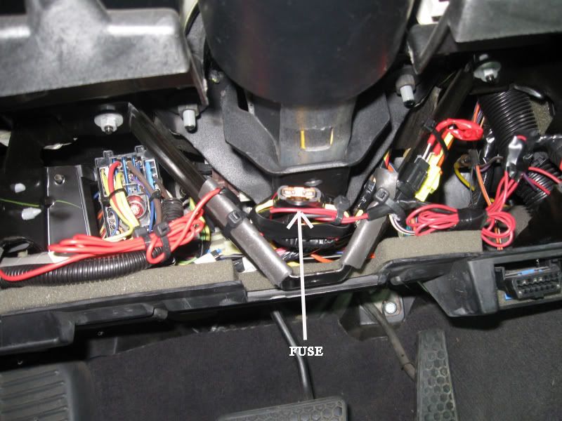
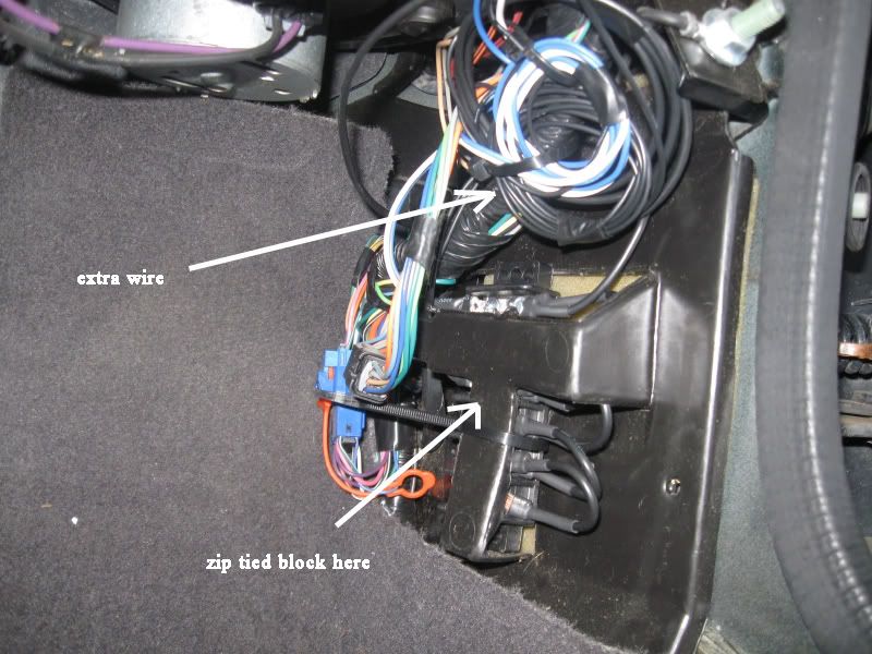
harness was ran under the carpet and exits just in front of the console. I tied it up behind the console after everything was ran.
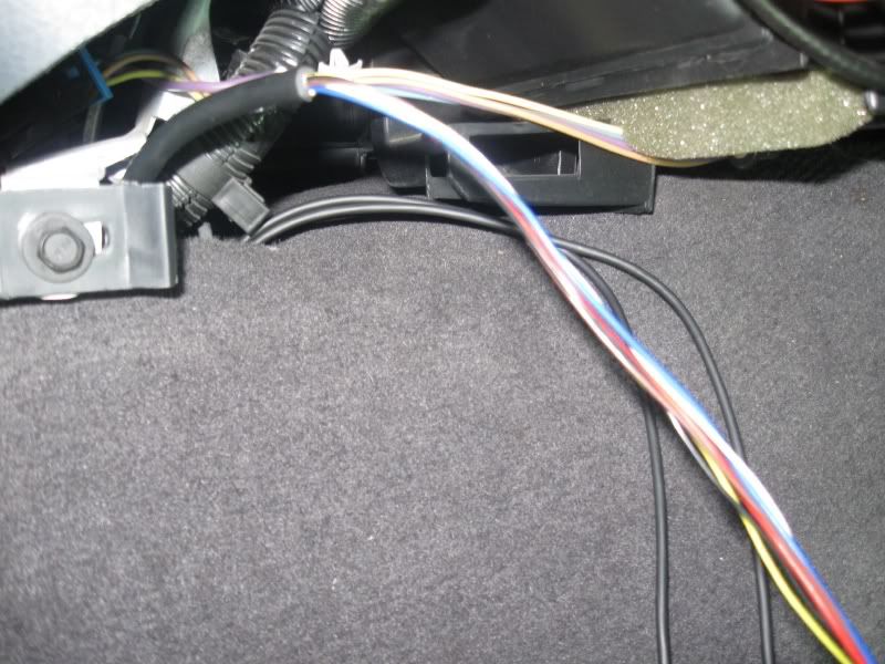
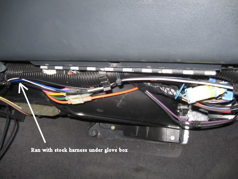
ran wires along stock harness to passenger footwell
zipped my block and extra wire here. What some may see as excessive wire I see as a service loop.
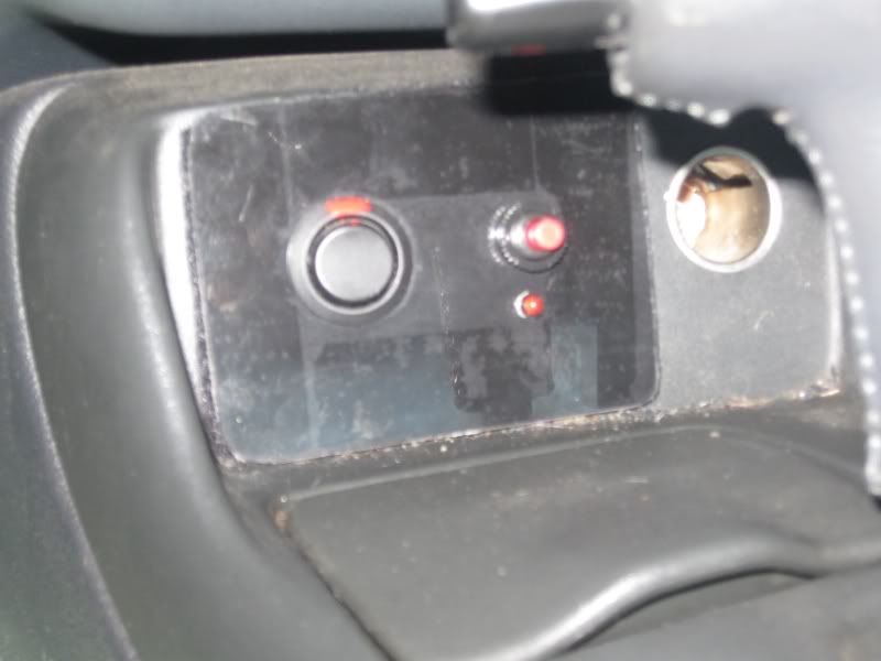
home made switch panel I made for the cutout and calibration button and LED
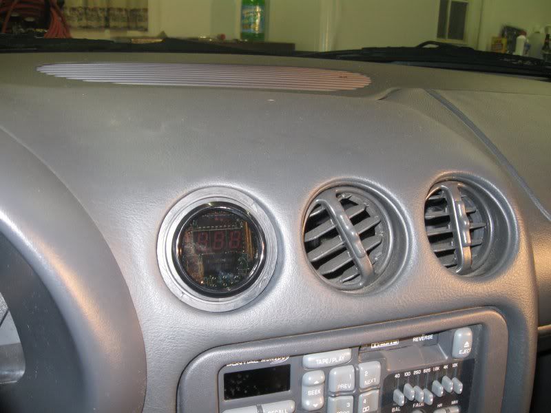
mounted the gauge in a vent with a home made mount
There are several spots I wish I would've done a better job. That switch panel needs redone so it's better looking. I'm not completely sure my grounds are going to work out like I planned just do to all the connections being the way they are. Overall it's a wait and see deal. I'll put some miles on the car in the next couple of weeks and see how it works.....not much else I can do.Last edited by 0rion; 03-17-2009 at 09:02 PM.
-
03-18-2009, 07:00 AM #2Member

- Join Date
- Feb 2007
- Location
- Council Bluffs IA
- Posts
- 192
nbm- 99 z28
I just got my lc-1 last wednesday. I haven't done anything aside of opening the box. been sick. what you did there with the grounds looks pretty good. one thing about the lc-1 that makes me scratch my head a bit is mounting the box under the car. kinda worry about it getting damaged there. I havent looked at the entire manual yet, but can you remove the sensor and the box under the car when your done tuning or does it have to stay there. reason I ask is I wasn't planning on using the guage. I just want to tune and be done with it till the next mod. sorry if I fired off too much at once. gettin ready to do myself. so tryin to get as much info as i can before I start.
can't wait to hear how it worked out for ya.
-
03-18-2009, 07:12 AM #3Veteran
- Join Date
- Aug 2005
- Location
- ohio
- Posts
- 22,554
98 Formula- 06 duramax
you can make it portable. I also have an LM-1 portable wideband and it would've been a much better choice for you as far as ease of getting it in and out of the car. If you plan on removing it you'll have to make a transfer box where you can unhook the wires from. It's gonna be a pain in the ass for you to remove it unless you put some time and thought into making it portable.
I ran my LM-1 under the car full time for the most part for the last 2-3 years with no issues. My car isn't a daily driver and hasn't seen rain in years other than 1 light sprinkle I got caught in last year so my unit hasn't really been put to the test. If you're concerned about it you could always make a small water resistant enclosure for the unit itself and that would be far easier than making it portable.
-
03-18-2009, 08:41 AM #4Member
- Join Date
- Feb 2007
- Location
- Council Bluffs IA
- Posts
- 192
nbm- 99 z28
yeah I kinda thought about putting it in some type of incloser too. or maybe,if at all possible mount it inside the arm rest and run the wires down to the sensor.
-
03-19-2009, 02:52 AM #5cutting and welding

- Join Date
- Mar 2008
- Location
- mercersburg pa
- Posts
- 6,443
hugger orange- 2004
another option. I DD mine in all kinds of weather so I didn't want my lc-1 box outside the car. I cut a 1 inch hole in the tranny tunnel to run the o2 sensor through and made a grommet for it, then mounted my box ontop of the tunnel, under the center console.
-
03-19-2009, 06:53 AM #6Veteran

- Join Date
- Nov 2005
- Location
- Florida
- Posts
- 10,467
Black- 1999 TA WS.6
Thats what I did. I need to re adjust things under the console, but my box is inside. Originally Posted by mark21742

-
03-20-2009, 03:25 PM #7Veteran
- Join Date
- Nov 2005
- Location
- Florida
- Posts
- 10,467
Black- 1999 TA WS.6
Hey Orion, check out what I found. I like it,

Yes, thats Velcro, and it works great!
The green wire is the 10 guage wire going to battery ground. But my guage is so far off, Im thinking the alternator is maybe having an affect. The guage never goes above 10.3? I have other issues with my cam swap underway so I stopped worrying about that for the time being. It reads fine on my HPtuner.
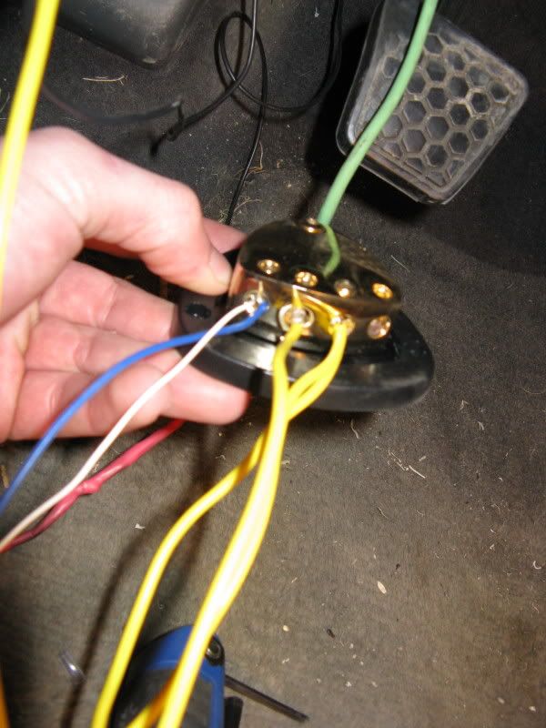
Whatda think Orion. Was this something more on the lines of what you were looking for? I found what you had at the local hardware store. But kept searching. Took my 7 places to find this one. Was it worth it? I dont know.
-
03-20-2009, 06:27 PM #8Veteran
- Join Date
- Aug 2005
- Location
- ohio
- Posts
- 22,554
98 Formula- 06 duramax
yep, that's close to what I was looking for. Which wire did you run to your gauge? The brown goes to the gauge and the yellow is set up for narrowband.
-
03-21-2009, 06:36 AM #9Veteran
- Join Date
- Nov 2005
- Location
- Florida
- Posts
- 10,467
Black- 1999 TA WS.6
Thats how I orginally had it ran. Then I was told that the brown is for the hptuners interface and the yellow is for the guage. Then I looked over the schmatic they give you, and that sounded right to me. Do I need to switch those two wires???? Originally Posted by 0rion
-
03-21-2009, 08:21 AM #10Veteran
- Join Date
- Aug 2005
- Location
- ohio
- Posts
- 22,554
98 Formula- 06 duramax
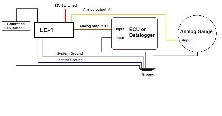
taken from the db gauge manual. You can leave it how you have it but you'll have to program the output to work with the gauge.
4. Connect the gauge’s BLUE wire to the LC-1’s Brown analog
output 2. The gauge is setup to work with the LC-1’s analog
output 2 factory default setting of 0v = 7.35 A/F and 5v =
22.39 A/F.
-
03-21-2009, 09:55 AM #11Veteran
- Join Date
- Nov 2005
- Location
- Florida
- Posts
- 10,467
Black- 1999 TA WS.6
I should probably just solder the BLUE wire to the the BROWN wire like they say in the Db gauge manual. Then run my YELLOW LC1 wire to the interface. Will that work better? Is this the reason my guage reading completely diffferent then my scanner?
-
03-21-2009, 09:56 AM #12Veteran
- Join Date
- Nov 2005
- Location
- Florida
- Posts
- 10,467
Black- 1999 TA WS.6
Because right now, the guage is operating off analog output #1. YELLOW
-
03-21-2009, 11:20 AM #13Veteran
- Join Date
- Aug 2005
- Location
- ohio
- Posts
- 22,554
98 Formula- 06 duramax
you won't necessarily have to rewire it. You can plug in with the laptop and set the output on the yellow wire (analog 1) to
0v = 7.35 A/F
5v =22.39 A/F
then you'll probably have to adjust the ground offset in hptuners to get them to sync up. I'll explain how to do that this evening. I'm getting ready to go somewhere in a few minutes. I'll edit this post and explain ground offsets.
-
03-22-2009, 12:10 AM #14Veteran
- Join Date
- Aug 2005
- Location
- ohio
- Posts
- 22,554
98 Formula- 06 duramax
I'll do a quick explanation of ground offsets and hopefully if I'm incorrect on any of it Frost or Mrr23 will step in and correct me but this is my understanding of it and how to do it.
First you have to set up a user defined pid. Do this by right clicking down where the EIO pid's go in the EIO input you're using and selecting insert.

then at the bottom of the list you click on user defined and conf. user defined

name it, abbreviate it, pick the sensor, and the units

notice to the left those numbers I have in there? Here's how you get those numbers. First you have to hook up to your LC1 with the laptop and program the outputs. I use 0v=10:1 afr and 5v=18:1 afr. Then I set the response speed for 1/6 under the advanced tab in logworks. Volts is divided by the range of both devices and then that is added to the low afr range. So my volt range is 5 and my AFR range is 8 and my low afr range is 10. 5 divided by 8 is .625 so that's volts/.625 +10.
Now you log with hptuners with the car up to temp and look for the difference and add subtract that to the low range (10) to make them line up correctly. There are a couple ways of doing it. You can go back into the LC1 with the laptop and program both voltages the same to get it to ouput the same or you can remove the sensor from the exhaust and do it in free air so the afr isn't bouncing around. The car needs to be running and the sensor needs to be up to temp no matter which way you do it.
-
03-23-2009, 08:50 AM #15Veteran
- Join Date
- Nov 2005
- Location
- Florida
- Posts
- 10,467
Black- 1999 TA WS.6
Thanks orion, im going to try this. I need to get my motor back together first. Hopefully that works, ncie write up... I love pictures.
-
06-16-2010, 12:07 AM #16Member

- Join Date
- Sep 2008
- Location
- Atlanta, GA,Ft.Walton Bch,FL
- Posts
- 447
- Blog Entries
- 1
silver- 99 ws6
W/B
I was thinking of running the o2 sensor though the driver side floor gromet
keeping controller inside car.
and having the o2 bung about ten inchs from the driver side LT collector.
my W/B is the AEM analog.
-
06-19-2010, 12:29 PM #17Veteran

- Join Date
- Feb 2009
- Location
- Mansfield, PA
- Posts
- 22,146
Black & Blue- '02 WS.6 / '07 Suburban
Got started on my LC1 and fuel pressure gauge install last night. There are no open switched receptacles in the fuse panel. I have my cutout where you have your wideband -- that is switched. Where you installed your cutout I test hot all the time. Is that the same on yours?
I'd rather not have a hot cutout switch as our car may set for extended periods. Based on what I am reading in the LC-1 materials, that thing is a bit sensitive and I wasn't sure about the cutout pulling power off the same feed. Any idea if this would be an issue?
-
06-19-2010, 01:08 PM #18Veteran
- Join Date
- Aug 2005
- Location
- ohio
- Posts
- 22,554
98 Formula- 06 duramax
I will have to go check again because it's been a couple years since I did the cutout but I believe that's key on hot on the car.....I'll have to check though. I know I did wire my cutout light to only be on while the blade is in motion ( light off in the open or closed position) so maybe that's why I did the light like that. Either way my car sits 99% of the time and I have no issues with it there.
-
06-19-2010, 04:36 PM #19Veteran
- Join Date
- Feb 2009
- Location
- Mansfield, PA
- Posts
- 22,146
Black & Blue- '02 WS.6 / '07 Suburban
I have 3 other open slots in the panel... open as in there is nothing in the holes at all. I may just have to use this single switched source to feed the cutout, LC-1 and pressure gauge. I really don't want to run a hot wire in from the engine bay boxes.
-
06-19-2010, 04:57 PM #20Veteran
- Join Date
- Aug 2005
- Location
- ohio
- Posts
- 22,554
98 Formula- 06 duramax
I would at least keep the LC1 on a separate circuit. Maybe run 1 hot for that and run another out and use a junction box like pictured above and draw power from that and fuse those individually.

 Reply With Quote
Thread Information
Users Browsing this Thread
There are currently 1 users browsing this thread. (0 members and 1 guests)
Similar Threads
-
2002 Firebird Trans Am / Install 7.5-7.625-4:10 gear install
By Buick455 in forum Automatic TransmissionReplies: 3Last Post: 07-09-2015, 05:17 AM -
Griffin radiator install, stand up radiator install
By 02Sweet in forum External EngineReplies: 12Last Post: 06-03-2012, 05:00 PM -
Install shop or DIY header install?
By dethinboots in forum External EngineReplies: 7Last Post: 09-24-2011, 06:35 PM -
Install help
By ChadSheehy in forum General HelpReplies: 5Last Post: 05-04-2010, 05:43 PM -
Bayarea...Nitrous install? recommend me a shop or member to do the install? Price?
By 2klude in forum Western MembersReplies: 5Last Post: 04-11-2007, 09:30 PM

Bookmarks