

Results 1 to 13 of 13
Thread: Upgrading Front Shocks
-
07-31-2013, 07:02 PM #1Veteran


- Join Date
- Feb 2009
- Location
- Mansfield, PA
- Posts
- 22,146
Black & Blue- '02 WS.6 / '07 Suburban
Upgrading Front Shocks
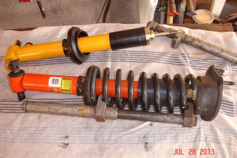
I finally got around to installing the set of Koni double adjustable shocks that I had purchased new in the box from a site member last year. Our car sees both street and track duty and was still sporting the original WS.6 DeCarbon shocks on all four corners together with stock springs. I have no interest in lowering our car, but am certainly up for better handling and improved 60' times at the track. Completely stock, our car ran consistant 60' times in the 2.1 to 2.2 second range. After suspension, exhaust, transmission, torque converter and tire upgrades, I was able to drop this down to a best yet of 1.69 seconds.
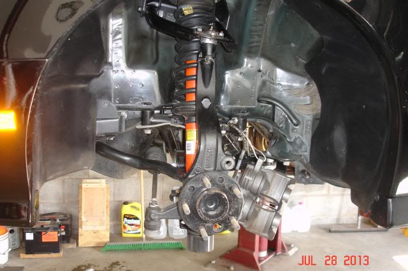
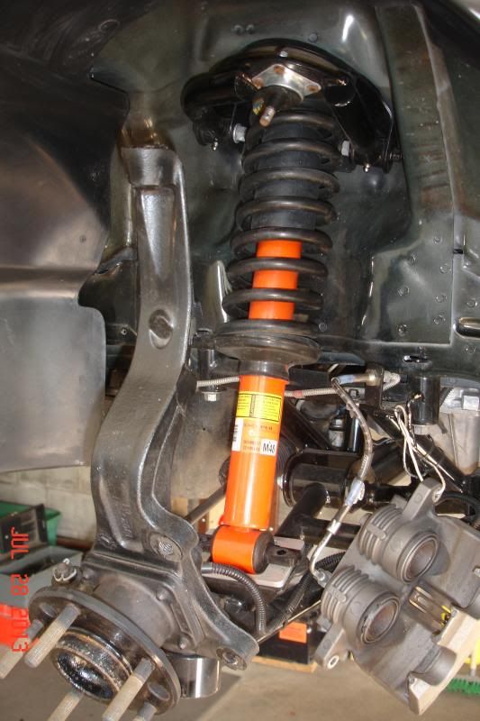
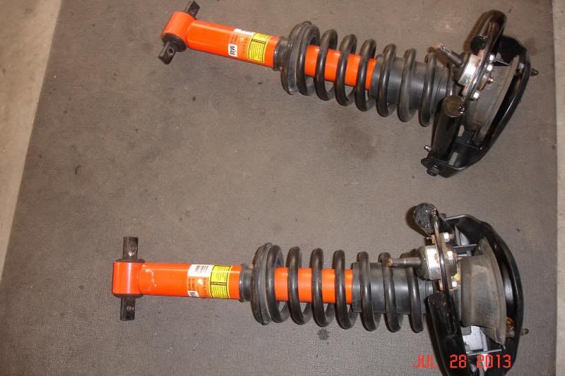
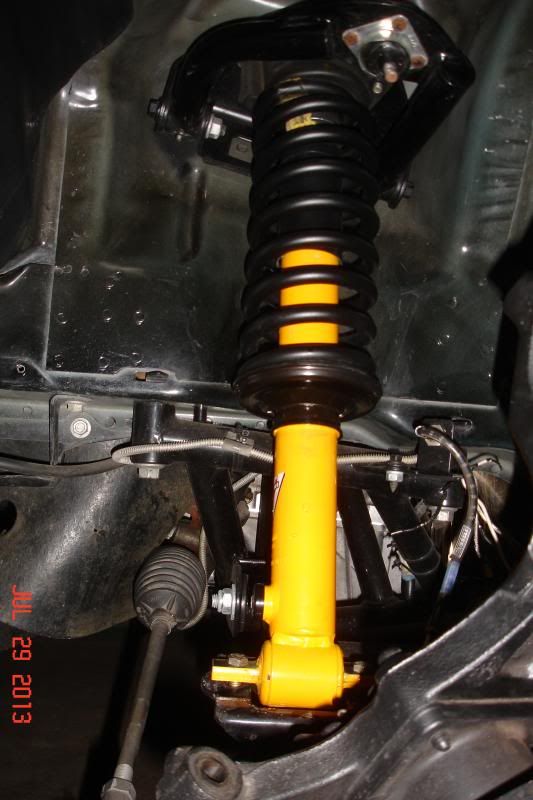
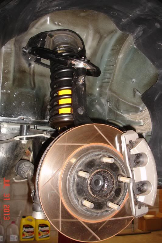
Struts or shocks? On F-bodies they are called "shocks" and this probably has to do with the fact that they are not attached to the steering knuckle. Instead, like typical shocks of old, they mount to the lower control arm and do not move when the steering wheel is turned. They are similar to struts, however, in the fact that the springs and shocks are an assembly and special tools and care are required to change out either component. This is the stock setup, after removal of the wheel and brake components, together with a UMI K-member and tubular control arms:
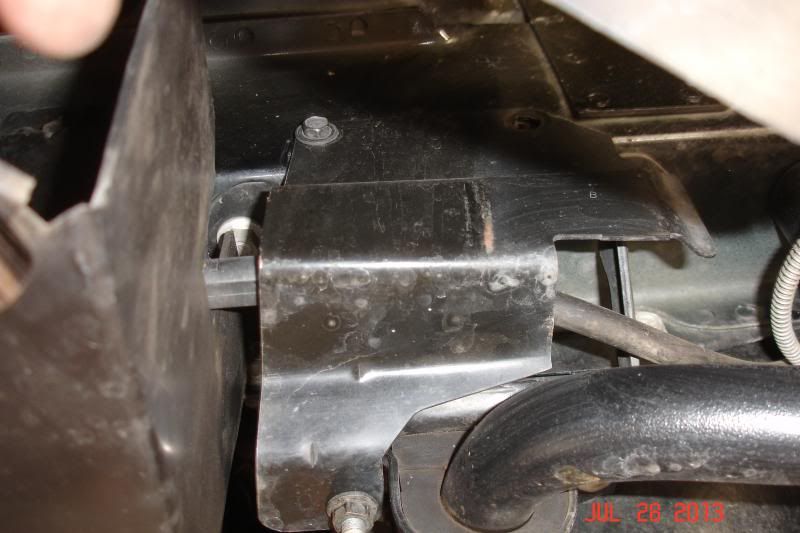
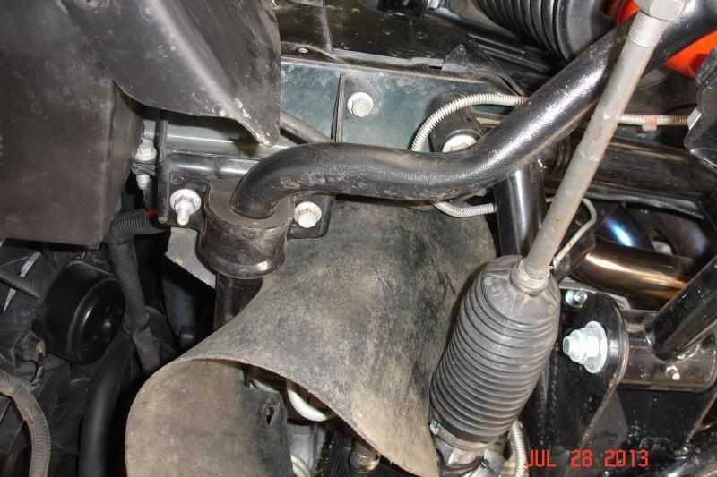
In order to drop down the lower control arm to remove the shock and spring assembly, it is necessary to remove the sway bar from the car. The bar is attached to the lower control arms by long bolts, spacers, washers and rubber or polyurethane isolators that are together referred to as a "sway bar end link". If rusted up, it is quite likely that they will break coming apart and new ones can be had at most parts stores. Upgrading to polyurethane bushings is always a good choice as the stock ones will usually be hammered at this point in a car's life. After pulling the end links, the bar can be unbolted from the frame rails, however, there is a bracket on the driver side that also has to be removed. In order to access the bolts, the lower splash shield has to be unbolted and the wheel house liner pulled out of the way. Two (2) 10 mm bolts attach the wheel house liner to the lower splash shield directly in front of the wheel, with the bolts being installed from underneath. You will then find two (2) more 10 mm bolts securing the top of the bracket (one bolt has already been removed in the first pic). The bracket sandwiches the front of the sway bar bushing and once out of the way the sway bar bushings can be unbolted and the sway bar removed. There is also a rubber splash shield that protects the alternator adjacent to the driver side bushing and removal of a metal washer clip will allow this to be pulled out of the way. In this case, looks are deceiving as the bar appears much heavier than it actually is due to the fact that it is hollow. You will still need a firm grasp on it and a friend can come in handy to get it safely out from under the car.
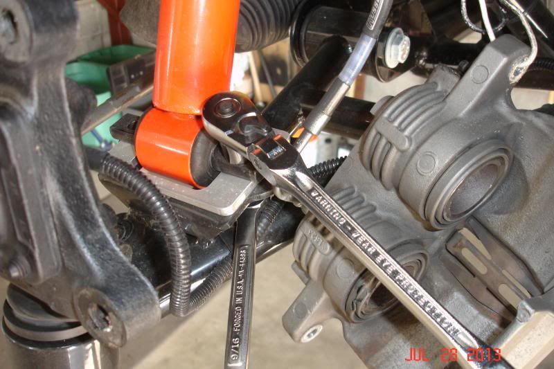
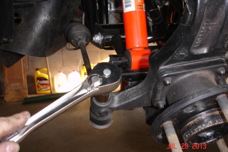
With the sway bar removed, and the brake calipers hung securely out of harms way, the cotter pins for the upper ball joints and tie rods can be removed and the nuts unscrewed until they are flush with the end of the stud. A sharp tap with a hammer will usually break each joint free - just be sure to hit it square and don't beat on it to the point that the threads are damaged. On our car, it took a single tap to knock out the tie rods and several taps to break the upper ball joints free. You can utilize a special fork tool, however, this risks damage to the grease boots and I have always had good luck with the BFH method. Once broken free, remove the nuts and then unbolt the lower shock mounts from the lower control arms. Then, simply pull down on the steering knuckle until it completely disengages the upper balljoint and allow it to hang out of the way.
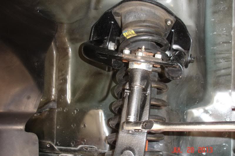
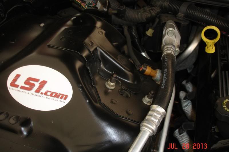
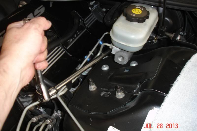
Up top, the shock and spring mounts must be unbolted from the wheel house on each side. For whatever reason, the General utilized a mismatched set of 15 mm nuts, 13 mm bolts and torx head bolts. The AC lines make workspace tight on the passenger side and the brake master cylinder blocks access on the driver side to the torx head bolts. The best thing to do is simply unbolt the master cylinder from the booster, unplug the wiring harness attached to the reservoir and then pull the master cylinder foward and up out of the way. The master is secured by two (2) 15 mm nuts and a swivel attachment on your ratchet allows for easy access to them. I also unbolted the ABS block to allow for more slack and had no issues gaining access to the bolts. Remove all the fasteners except for the front outside nut on each side. Leave this on the end of the stud to keep the shock and spring assembly from exiting prematurely onto your toes.
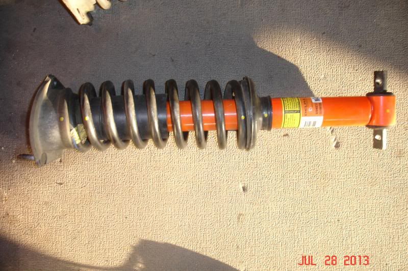
Moving back under the car, you can now pull down on the lower control arm, using the steering knuckle as a lever, and then pull the bottom of the shocks out of their mounting plates. Then, holding onto the assembly, reach up top and remove the remaining nut from the top of the wheel house and carefully pull the springs and shock assembly out from under the car. The upper control arm will come with it, but is not secured to the assembly so take care not to turn it upside down as it will fall off. It is best to keep all the left side stuff and right side stuff separated so as not to cross anything up -- the upper control arms are marked as to which side they are from. Once removed, simply pull the upper control arm off and you can then begin work on disassembling the spring and shock.
Last edited by pajeff02; 07-31-2013 at 07:07 PM.
-
07-31-2013, 07:37 PM #2Veteran
- Join Date
- Feb 2009
- Location
- Mansfield, PA
- Posts
- 22,146
Black & Blue- '02 WS.6 / '07 Suburban
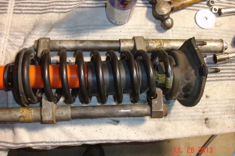
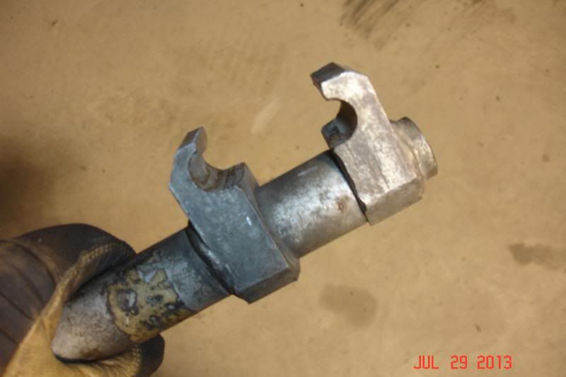
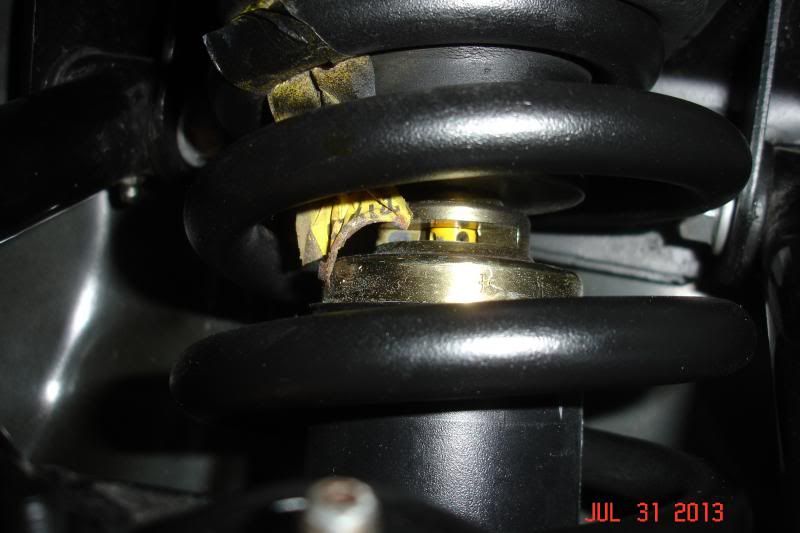
They do make a special hydraulic tool for compressing both struts and spring/shock assemblies such as this, however, they are usually found only in dealership garages or area shops. If you do not have the ability or tools to safely remove the spring, please STOP, and take it somewhere to be done. In our case, I have both internal and external coil spring compressors and the external style is what is required. Before proceeding, it is a good idea to mark the orientation of all the pieces. I used a paint pen to make a yellow dot on each component -- including the top and bottom of the spring. The spring is under significant pressure and this has to be completely relieved before removing the retaining nut at the top of the shock. On a workbench, install the spring compressors as shown and then begin evenly compressing the spring going back and forth between each one. After working on the first one, I modified our compressor by cutting down the inside lips by approximately 3/16" as the coils of the spring are spaced closely together and I had difficulty both inserting and removing the tools. The spring is compressed sufficiently when it will "wiggle" freely between the upper and lower mounts.
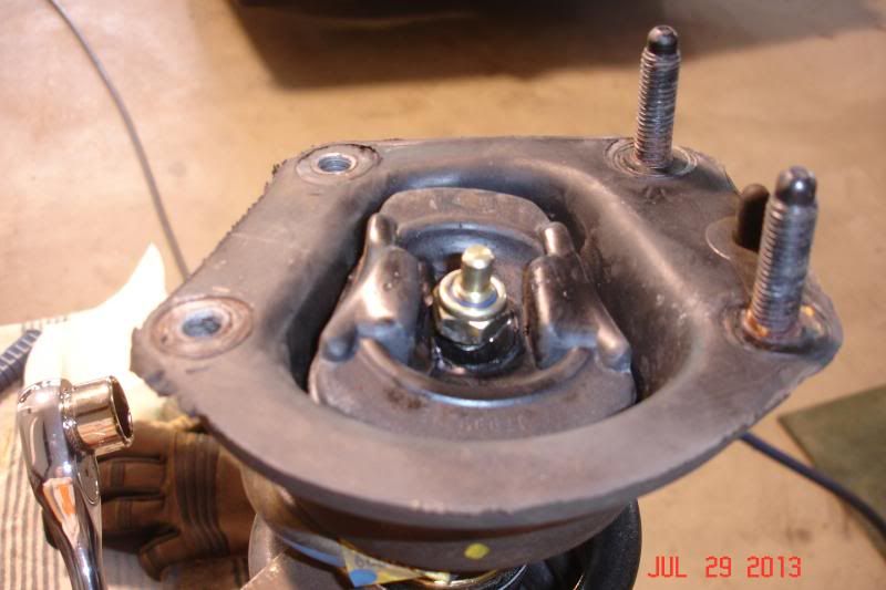
At this point, the top nut can be removed from the shock and the isolators and top plate pulled off. In some cases, the nut will be so rusted to the old shock that it may need to be cut off. I was lucky and the nuts came off easily with an air impact. Note that the shaft onto which they are bolted can spin and that you may need to hold it in some fashion. How you do this may depend on whether you ever plan to use or sell your stock units, but destructive disassembly may be the only method that works. After the top pieces are all removed, the shock can be pulled out of the bottom of the spring and parts can be cleaned up and painted before installing the new shock. With the Konis, there is a large flat washer that goes on top of the shock before the rubber insulator. Again, the shaft has to be held from turning and you cannot simply air gun the nut into place. Also, on the Konis you absolutely have to orient the window for the rebound adjustment so that it faces out towards the wheel -- this is very important! Make sure that it doesn't accidentally spin out of alignment during the reassembly process or you will have to re-compress the spring to turn it.
The torque spec on the top nut is something in the range of 20-25 lb.ft. In reality, there is really no way to properly torque it and hold the shaft from turning, so just get it tight and call it good. I have a set of sockets that are hollow all the way through and even these wouldn't work to tighten the nut as there simply isn't enough height to get on the flat spot of the shaft. After everything is back together, the installation into the car is simply a reversal of removal and goes fairly quickly. Just be sure to reinstall the upper control arms onto the shocks before slipping them into place. I may have forgotten this in my excitement on the first go around...
Torque specs are as follows:
Upper ball joint - 39 lb.ft.
Lower shock mount bolts - 48 lb.ft.
Upper shock mount nuts - 32 lb.ft.
Upper shock mount bolts - 37 lb.ft.
Brake master cylinder nuts - 21 lb.ft.
Outer tie rod nuts - 35 lb.ft.
Sway bar bracket - 41 lb.ft.
Sway bar end link - 17 lb.ft.
Brake caliper bracket to steering knuckle - 74 lb.ft.
Brake caliper pin bolts - 23 lb.ft.
Don't forget to install new cotter pins and tighten (do not loosen) the castle nuts to align the holes if necessary. Also, it would be a good idea to protect the lower portion of the new shocks with painters tape during the assembly process.
-
07-31-2013, 07:42 PM #3Member

- Join Date
- Jun 2009
- Location
- lisle, il
- Posts
- 290
Red, Black- 98 T/A M6, 79 T/A 6.6L
Ive done this a couple times in the past year. Be sure to remind everyone if ordering new strut mounts that the 'bearing' or big rubber n metal 'washer' also need to be purchased in order to prevent the top of the strut and nut from tearing thru the new shock mount. You dont easily notice these if you dont tear apart the old...
Ask me how I know.
Oh and great write up n even better pics
-
07-31-2013, 07:44 PM #4Veteran
- Join Date
- Feb 2009
- Location
- Mansfield, PA
- Posts
- 22,146
Black & Blue- '02 WS.6 / '07 Suburban
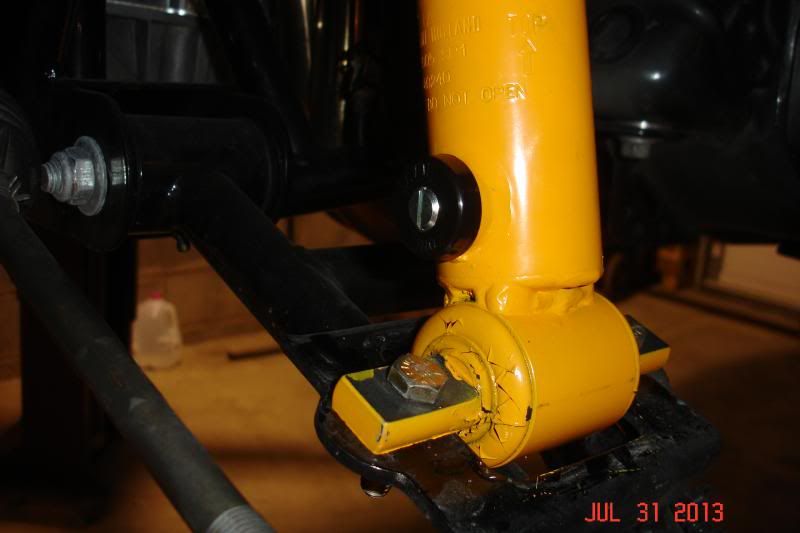
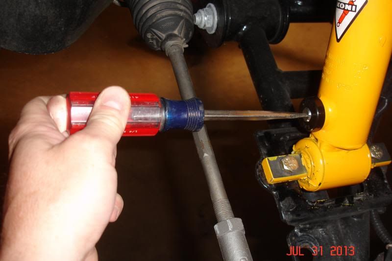
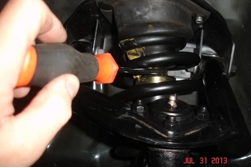
The final step is adjustment of the new shocks. The Konis have adjustable rebound and compression. The rebound adjustment is at the base of the shock and is set using a flat blade screwdriver. I believe there are twelve (12) separate settings and I went one click up from full soft in order to allow the shock to extend easily for better weight transfer. On the street, I may click this up another 3 or 4 notches.
The compression setting is completed through the window at the top of the shock. I used an angled pick, although I believe there was a tool in the box that I have stashed somewhere. Again, I think there are something like twelve (12) settings and on this I went up four (4) turns from full soft.
Koni recommends keeping the settings the same from side to side and it will take some driving to get them adjusted to where they work best. I did elect to leave the sway bar off the car for the time being as we are heading to the track on Saturday.
-
08-01-2013, 08:36 AM #5Member

- Join Date
- Apr 2012
- Location
- Iowa
- Posts
- 207
2002 Trans Am WS6 - Red- 2013 Chevy Traverse LTZ
Wow. Great writeup. See how clean that car is..?
-
08-01-2013, 11:36 AM #6Spaz is My Mentor


- Join Date
- Feb 2009
- Location
- Florida Man Status Acheivement
- Posts
- 11,785
Navy Blue Metallic- 98 T/A, 00 FBVert, 78T/A
Great write up Jeff
 Originally Posted by initechpeter

so clean you can eat off of.
-
08-01-2013, 01:35 PM #7Veteran
- Join Date
- Feb 2009
- Location
- Mansfield, PA
- Posts
- 22,146
Black & Blue- '02 WS.6 / '07 Suburban
Thanks, guys. Been meaning to get to this project for quite a long time now. I think Keith finally gave up on me.
-
08-01-2013, 01:43 PM #8Veteran

- Join Date
- Oct 2008
- Location
- Wherever life takes me
- Posts
- 12,526
Red- 02 35th LE Camaro SS
How do you like your new shocks? Have enough seat time to feel any noticeable difference?
Boost gets you laid, unless your name is Jon.
-
08-01-2013, 05:49 PM #9Veteran
- Join Date
- Feb 2009
- Location
- Mansfield, PA
- Posts
- 22,146
Black & Blue- '02 WS.6 / '07 Suburban
The car does feel "smoother" on the road, but that could just be a psychological thing. Only have around 30 miles on them so far. I will have Zach watch the front end at the track and try for some pics to see how it reacts coming off the line.
-
10-10-2013, 02:53 PM #10Senior Member

- Join Date
- Feb 2006
- Location
- Orange County, NY
- Age
- 48
- Posts
- 2,693
always dirty- 2013 Ram 2014 Caddy ATS
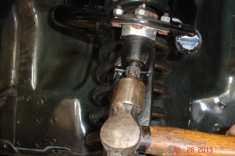
I noticed you smacked the threaded part of the ball joint. i usually hit the spindle, right where the tapered part of the ball joint goes in. Less likely to damage the threads. Sometimes there is a flat spot to hit with the hammer. You can see a flat spot for the tie rod.
-
10-12-2013, 04:45 AM #11Veteran
- Join Date
- Feb 2009
- Location
- Mansfield, PA
- Posts
- 22,146
Black & Blue- '02 WS.6 / '07 Suburban
I always back the castle nut off until it is flush with the head of the stud. Never had an issue doing it that way, but I will keep your suggestion in mind for future jobs. Thanks!
-
10-12-2013, 07:20 PM #12Former Mopar Man

- Join Date
- Jun 2011
- Location
- Branchville, NJ
- Posts
- 3,111
Silver & Blue- 02 Camaro SS, 04 GTO
Never. I knew it was just a matter of time. Now it's time to do the rears. Originally Posted by pajeff02
My ride is a 2002 Camaro SS SLP #3296 with 30k, LTH, 3" Y, CME, Frost tune, K&N, ported TB, Blackwing lid, Bellows, MSD, Denso Iridium, and 85mm MAF, Bilsteins, Eibach springs, SLP strut brace, Adj. Panhard, TA Girdle, UMI, Pro 5.0, Nitto NT555
My wife has a 2004 GTO with the rare SAP, 18" wheels, K&N Cold Air System, MSD, Ported TB, Frost tune, Denso Iridium, Flowmaster cat-back, 3200 Yank, 75k
-
10-13-2013, 04:26 PM #13Veteran
- Join Date
- Feb 2009
- Location
- Mansfield, PA
- Posts
- 22,146
Black & Blue- '02 WS.6 / '07 Suburban
 Exactly. Good winter project.


 Reply With Quote


Thread Information
Users Browsing this Thread
There are currently 1 users browsing this thread. (0 members and 1 guests)
Similar Threads
-
Help: front shocks
By Siciliano15 in forum Suspension and HandlingReplies: 15Last Post: 10-15-2009, 09:40 PM -
Front and Rear QA1 shocks with front QA1 springs
By 1BadCamaro in forum Parts For Sale / TradeReplies: 1Last Post: 08-09-2007, 04:16 AM -
front shocks
By 1_bad_TA in forum Suspension and HandlingReplies: 0Last Post: 06-19-2007, 01:32 AM -
LS1 Oil Pan and Front Shocks
By AshWS6 in forum Parts For Sale / TradeReplies: 0Last Post: 03-01-2007, 01:55 PM -
Upgrading shocks with a stock suspension
By Zapper2003 in forum Suspension and HandlingReplies: 4Last Post: 02-26-2007, 02:16 PM

Bookmarks